Example: High Speed DAC/ADC
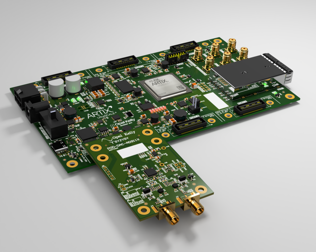
A FrontPanel Platform GUI enables users to generate and view signals with multiple frequency vectors using the SZG-DAC-AD9116 and the SZG-ADC-LTC226x on an XEM8320-AU25P. The FrontPanel Subsystem Vivado IP Core stimulates our HLS Fast Fourier Transform (FFT) cores to combine and convert these vectors into a time domain digital output signal and vice versa. A signal generator only version using an XFP GUI + Lua scripting is also provided.
This sample paired with an Opal Kelly FPGA Development or Integration module provides a great starting template for those interested in DSP applications. The sample can be enhanced by additional DSP processing through additional user defined AMD-Xilinx’s HLS cores, or through AMD-Xilinx’s Filter, Modulation, Trig Functions, etc. DSP IP Cores.
Artix-7 and Legacy ADC and DAC Example Support Information
We currently have simpler ADC and DAC example designs available on our open source Github that target the XEM7320 and the XEM8320. Note, these are no longer supported or maintained.
The ADC design is a simple scope that uses Python to display the signals from the ADC. More information is available in the READMEs for the desired XEM module.
The DAC design features AM/FM modulation and can pipe audio into the design to modulate it over a carrier wave with the requested parameters. You can learn more about it on our blog, here.
Resources
- GitHub: Opal Kelly’s HLS Fast Fourier Transform (FFT) Core
A synthesizable and scalable pipelined fixed-point Decimation-in-Frequency FFT and IFFT FPGA library for use with AMD-Xilinx’s High Level Synthesis (HLS). - Github: DAC/ADC Example Design
A complete sample using HLS FFT and IFFT cores. This sample targets the XEM8320, SZG-DAC-AD9116, and SZG-ADC-LTC226x.
Learning Objectives
Users will learn the following:
- Set up and use an XFP GUI with FrontPanel Scripting and/or a FrontPanel Platform GUI for control of FrontPanel-enabled gateware.
- Utilize the open-source JavaScript library Chart.js for data acquisition and oscilloscope display.
- Create IPI Block Designer projects utilizing the FrontPanel Subsystem Vivado IP Core.
- Get introduced to a workflow that incorporates FrontPanel and AMD-Xilinx’s High Level Synthesis (HLS) components.
Getting Started
Requirements
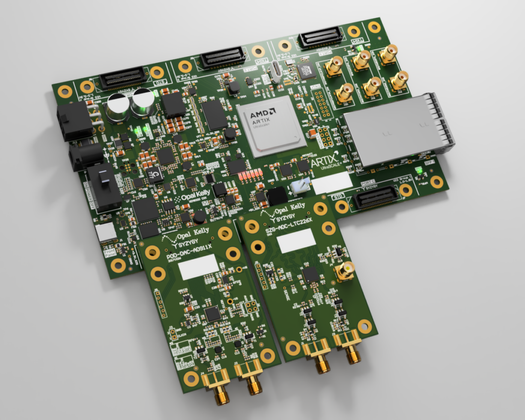
- Hardware
- XEM8320-AU25P
- SZG-DAC-AD9116 on Port A
- SZG-ADC-LTC226x on Port B
- Only required for FrontPanel Platform Signal Generator + Spectrum Analyzer application
- Oscilloscope
- Only required for XFP Signal Generator application
- Note: For best results, use an oscilloscope with 200 MHz bandwidth to best represent the SZG-DAC-AD9116’s full Nyquist bandwidth of 62.5MHz.
- Software
Two applications are available as options for interfacing with the design:- FrontPanel Platform Signal Generator + Spectrum Analyzer Github release
DAC-ADC-ExampleDesign-1X-v2.0.asar- Select the
DAC-ADC-ExampleDesign-12-v2.0.asarorDAC-ADC-ExampleDesign-14-v2.0.asardepending on the SZG-ADC you are using.
- Select the
- FrontPanel v6.0.0 (beta) or later
- XFP Signal Generator
FFTSignalGenerator.xfpFFTSignalGenerator.lua- FrontPanel 5.2.12 or later
DAC-ADC-ExampleDesign-ADC-12-v2.0.bitfor the SZG-ADC-LTC2264-12DAC-ADC-ExampleDesign-ADC-14-v2.0.bitfor the SZG-ADC-LTC2268-14
- FrontPanel Platform Signal Generator + Spectrum Analyzer Github release
FrontPanel Platform Signal Generator + Spectrum Analyzer
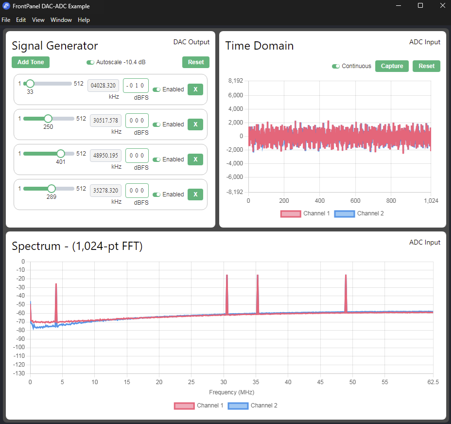
The goal of this tutorial is to use the provided prebuilt ASAR in-hardware to generate a four-tone signal and verify the time and frequency domain characteristics of the signal.
The Signal Generator component of the user interface will be used to configure the IFFT to produce the signal that is output through the SZG-DAC-AD9116. The signal will be routed to the SZG-ADC-LTC226x and the FFT to produce time and frequency domain plots.
Hardware Setup
- Power off the XEM8320-AU25P.
- Connect a SZG-DAC-AD9116 to port A on the XEM8320-AU25P.
- Connect a SZG-ADC-LTC226x to port B on the XEM8320-AU25P.
- Connect one of the outputs of the SZG-DAC-AD9116 to one of the inputs of the SZG-ADC-LTC226x.
- Power on the XEM8320-AU25P using a 12-volt supply.
- Connect the XEM8320-AU25P to a PC using a USB-C cable.
FrontPanel Application Setup for FrontPanel Platform GUI
- Open FrontPanel 6.0.0 beta or later.
- Select the DAC-ADC-ExampleDesign-1X-v2.0.asar you are using in the now open file browser.
- Select the DAC-ADC-ExampleDesign-12-v2.0.asar or DAC-ADC-ExampleDesign-14-v2.0.asar depending on the SZG-ADC you are using.
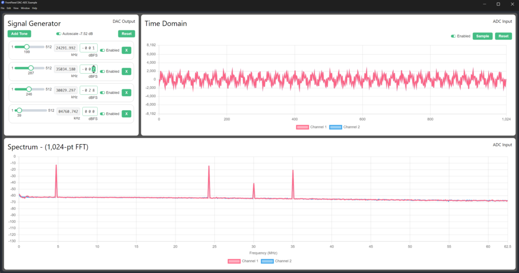
Signal Generator Configuration
- Enable Auto Scaling.
- Enable the first four frequency vectors.
- Set the first frequency vector to bin number 199 and -1 dBFS.
- Set the second fequency vector to bin number 287 and -7 dBFS.
- Set the third frequency vector to bin number 246 and -28 dBFS.
- Set the fourth frequency vector to bin number 39 and 0 dBFS.
- The Time Domain chart should show the waveform of four-tone signal.
- The Spectrum chart should show the frequency domain representation of the four-tone signal.
XFP Signal Generator Example
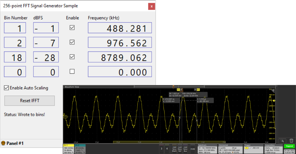
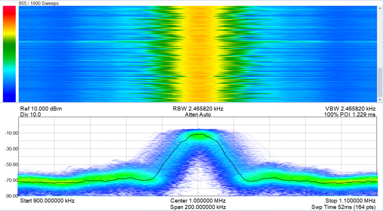
The goal of this tutorial is to produce a three-tone wave using the provided prebuilt bitfile in-hardware and capturing the result on an oscilloscope.
Hardware Setup
- Power off the XEM8320-AU25P.
- Connect a SZG-DAC-AD9116 to port A on the XEM8320-AU25P.
- Power on the XEM8320-AU25P using a 12-volt supply.
- Connect the XEM8320-AU25P to a PC using a USB-C cable.
Oscilloscope Setup
- Connect an oscilloscope probe to either SZG-DAC-AD9116 output’s center pin, and ground the signal on the outer SMA connector, if using a standard probe.
- Set the oscilloscope to center 0 volts, with a vertical range of +/- ~1 volt.
FrontPanel Application Setup
- Open FrontPanel 5.2.12 or later.
- Click the Download FPGA Configuration button.
- Select the bitfile that corresponds to the SZG-ADC-LTC226x.
- SZG-ADC-LTC2264-12 requires
DAC-ADC-ExampleDesign-ADC-12-v1.0.bit - SZG-ADC-LTC2268-14 requires
DAC-ADC-ExampleDesign-ADC-14-v1.0.bit
- SZG-ADC-LTC2264-12 requires
- Click the Load FrontPanel Profile button and select
FFTSignalGenerator.xfp.
Note:FFTSignalGenerator.luaneeds to be in the same directory asFFTSignalGenerator.xfp.
Signal Generator Configuration
- Click Reset IFFT.
- Enable Auto Scaling.
- Enable bins 1, 2, and 3. Leave bin 4 disabled.
- Set bin 1 to bin number 1, bin 2 to bin number 2, and bin 3 to bin number 18.
- Use your mouse’s scroll wheel to set their corresponding dBFS values to -1, -7, and -28.
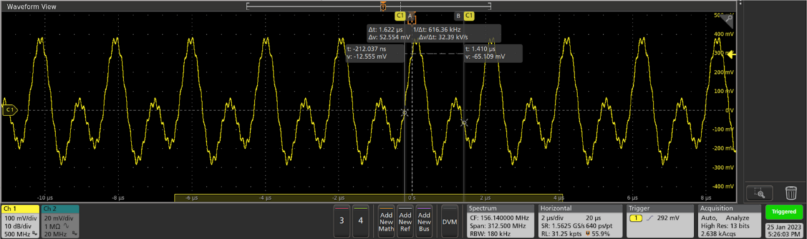
- There should now be a three-tone sine wave displaying on the oscilloscope, as shown below.
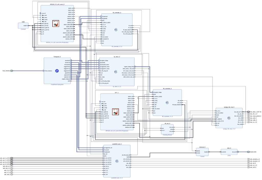
How-To Setup the Project
We provide various build scripts for instructing Vitis HLS to build our FFT core, creating the Vivado project, configuring the required IP Cores, and constructing the IPI Block Design Project. The end result of this How-To is the construction of the following Vivado IPI Block Design project:
This design requires the following to build:
- Vitis HLS
Notice: Our supported version is v2023.2. Versions outside of this are not guaranteed to be maintained. - Vivado
Notice: Our supported version is v2023.2. Versions outside of this are not guaranteed to be maintained. - Vivado IP Cores’ Distribution v1.0.2 or later
- XEM8320-AU25P Board file v1.2 or later
- Latest DAC-ADC-ExampleDesign-vX.Y release Source Code (zip or tar.gz)
Windows
- Follow How-To Install for the XEM8320-AU25P’s Board file v1.2 or later.
- Follow Add IP Cores’ Distribution to Vivado for Vivado IP Cores’ Distribution v1.0.2 or later. The location you installed this Distribution to will be used in step 6.
- Extract the sample’s release’s Source Code (zip or tar.gz).
- Open a command prompt and
cdto theDAC-ADCexample folder.cd C:/pathToDownload/design-resources-DAC-ADC-ExampleDesign-vX.Y/ExampleProjects/DAC-ADC
Note: PowerShell won’t work, Command Prompt must be used. - Run the
settings64.batfile in the Vitis HLS and Vivado installation directories.path/to/vitis/2023.2/settings64.batpath/to/vivado/2023.2/settings64.bat - Run the appropriate .bat file for your SZG-ADC-LTC226x target:
– For SZG-ADC-LTC2264-12, usewindows_create_project-adc-12.bat.
– For SZG-ADC-LTC2264-14, usewindows_create_project-adc-14.bat.
Provide the path to the Vivado IP Cores’ Distribution as an argument:windows_create_project-adc-12.bat C:/pathToDownload/FrontPanel-Vivado-IP-Dist-vX.Y.Z
Linux
- Follow How-To Install for the XEM8320-AU25P’s Board file v1.2 or later.
- Follow Add IP Cores’ Distribution to Vivado for Vivado IP Cores’ Distribution v1.0.2 or later. The location you installed this Distribution to will be used in step 6.
- Extract the sample’s release’s Source Code (zip or tar.gz).
- Open a terminal and
cdto theDAC-ADCexample folder.cd C:/pathToDownload/design-resources-DAC-ADC-ExampleDesign-vX.Y/ExampleProjects/DAC-ADC - Run the
settings64.shfiles in the Vitis HLS and Vivado installation directories.source path/to/vitis/2023.2/settings64.shsource path/to/vivado/2023.2/settings64.sh - Run the appropriate .bat file for your SZG-ADC-LTC226x target:
– For SZG-ADC-LTC2264-12, uselinux_create_project-adc-12.bat.
– For SZG-ADC-LTC2264-14, uselinux_create_project-adc-14.bat.
Provide the path to the Vivado IP Cores’ Distribution as an argument:linux_create_project-adc-12.bat C:/pathToDownload/FrontPanel-Vivado-IP-Dist-vX.Y.Z
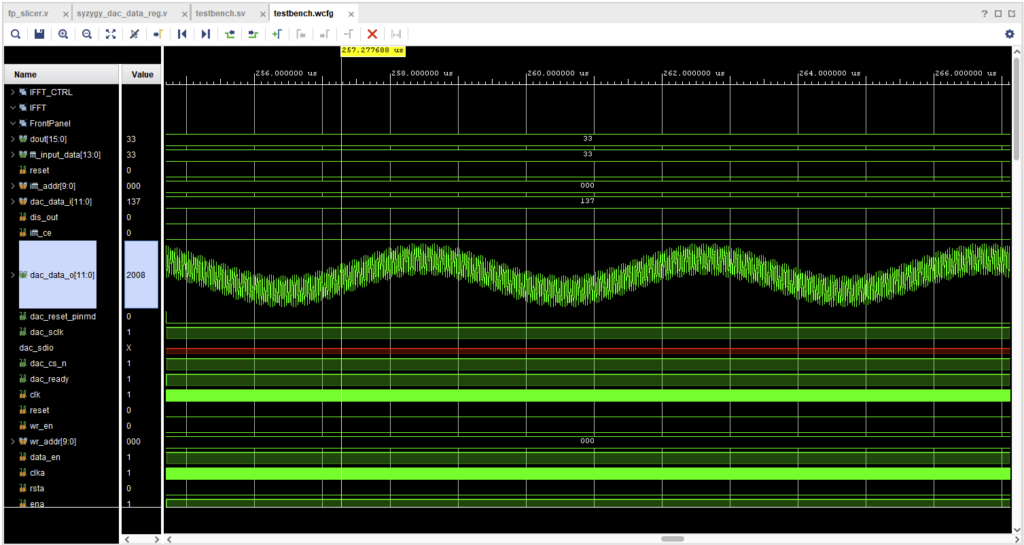
How-To Run the Behavioral Simulation
We utilize the Behavioral Simulation features of the FrontPanel Subsystem Vivado IP Core to provide a simulation of the design. The end result of this How-To is the creation of a simulation waveform for a two-tone wave with simulated PipeOut reads of the FFT calculations:
- Follow How-To Setup the Project
- In Vivado, launch Flow>Run Simulation>Run Behavioral Simulation
- Launch Run>Run All
How-To Generate the Bitfile
- Follow How-To Setup the Project
- In Vivado, launch Flow>Generate Bitfile
How-To Build the FrontPanel Platform Application
Requirements
- Latest DAC-ADC-ExampleDesign-vX.Y release Source Code (zip or tar.gz)
- Install prerequisites from the Development Guide
- FrontPanel 6.0.0 installed
Steps
- Extract the sample’s release’s Source Code (zip or tar.gz).
cdto the Platform folder:cd C:/pathToDownload/design-resources-DAC-ADC-ExampleDesign-vX.Y/ExampleProjects/DAC-ADC/Software/FP-Platform- Place the prebuilt bitfile for your SZG-ADC provided in the Github Release in the
assetsfolder- DAC-ADC-ExampleDesign-ADC-12-v2.0.bit or DAC-ADC-ExampleDesign-ADC-14-v2.0.bit
- Ensure the program will use the correct bitfile by changing which line is commented out on this line in
src/App.tsx: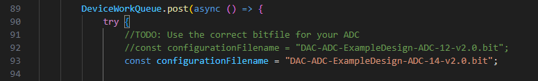
- I.e., if you are using the SZG-ADC-LTC2264-12, uncomment line 92 and comment out line 93.
- Install the dependencies:
npm install - Build the application:
npm runpack - Open the FrontPanel Platform beta application and select the app.asar in the
outputfolder to run the DAC-ADC example application.
Gateware Architecture Reference
Below we define terms and three important data flow stages for this sample:
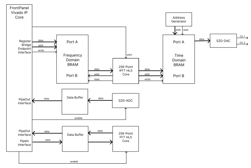
- Frequency Domain BRAM – Contains the 256 frequency domain vectors the FFT computes with.
- IFFT Start – The XFP GUI with FrontPanel Scripting or the FrontPanel Platform application communicate with the FrontPanel Subsystem Vivado IP Core generated FrontPanel HDL endpoints to store the Vector Set into the Frequency Domain BRAM. A custom RTL Slicer is used to distribute control signals throughout the design.
- FFT Enable – Enables the FFT core to calculate the SZG-ADC input.
Software
FrontPanel Platform Application GUI Reference

Signal Generator Panel
The components of this panel are used to control the output of the DAC.
- Add Tone – This appends a new frequency vector component to the list.
- Autoscale – If enabled, will scale the output signal so that it does not exceed the maximum in order to prevent clipping.
- Frequency Vector
- Bin Slider – This sets the frequency bin number used to configure the IFFT.
- Frequency (kHz) – The frequency corresponding to the bin number selected.
- Magnitude (dBFS) – DeciBel Full Scale. 0 = full power, -120 = nearly off.
- Enabled – If checked, the frequency vector will be included when computing the output signal.
- X – Removes the frequency vector component from the list.
- Reset – Resets the signal generator components of the design.
Time Domain and Spectrum Panels
The components of these panels are used to retrieve and visualize the input of the ADC.
- Continuous – If enabled, will continuously retrieve frames of 1,024 samples acquired from the ADC.
- Sample – Retrieves a single frame of 1,024 samples acquired from the ADC.
- Reset – Resets the data acquisition components of the design.
- Time Domain Chart – Displays a frame of 1,024 samples retrieved for each of two separate channels.
- Spectrum Chart – Displays the results retrieved from the FFT corresponding to the samples acquired from the ADC.
XFP GUI Reference
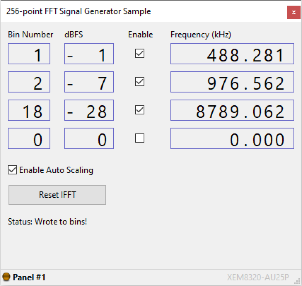
The user interface shown above has the following components to control the behavior of the FFT signal generator:
- Bin Number – This selects a frequency bin number in the FFT to activate, from 0 to 127.
- dBFS – DeciBel Full Scale. 0 = full power, 120 = nearly off.
Note: You must use your scroll wheel to input into this entry - Enable – If unchecked, disables the bin. Also discludes the dBFS value from any Auto Scaling calculations.
- Frequency (kHz) – The frequency of the specified Bin Number.
- Enable Auto Scaling – If enabled, will prevent the sum of all the bin values (calculated from dBFS) from going over the maximum. This will prevent clipping. For example, if two bins were enabled with a dBFS of zero, the Lua script will halve the components to the selected bins and the output signal from the SZG-DAC will not be clipping.
- Reset IFFT – Resets the design.
Limitations
A limitation of the XFP and FrontPanel Platform applications provided, is the inablitiy to set the phase of the frequency domain vectors of the Signal Generator. This involves specifying the complex component of the frequency bins. The functionality to do this is present in the gateware, but is not currently implemented in the applications provided with the example.
Release Notes
Our supported releases for the FFT Signal Generator sample are located on GitHub at:
opalkelly-opensource/design-resources Releases
High Speed DAC/ADC 2.0
- FrontPanel Platform Beta GUI updates
- Bitfiles are included in the ASAR file.
High Speed DAC/ADC 1.0 (Deprecated)
- Renamed design
- Added ADC + IFFT functionality
- FrontPanel Alloy GUI functionality
FFT Signal Generator 1.0
- Initial Creation
- Bitfile generated using the following tool versions:
Vivado v2022.1
Vitis HLS v2022.1
Vivado IP Cores’ Distribution v1.0.2
XEM8320-AU25P Board file v1.2