Sample: First
The First FrontPanel sample contains the following files:
| FILE | DESCRIPTION |
|---|---|
| First.xfp | FrontPanel profile (text-readable XML). |
| first.bit | Xilinx configuration file produced from ISE. |
| Verilog/First.v | Verilog description of the project’s toplevel. |
| Verilog/First.ucf | Xilinx constraints file containing pin location constraints. |
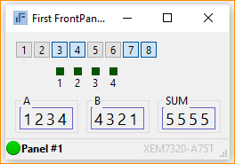
When the profile is loaded into FrontPanel, it creates a user interface that looks like this:
Toplevel Description
The file First.v contains the Verilog description of the project, including all pins which are physically connected to the FPGA. It’s entire contents are listed below: (Note that, while the USB version is shown here, the PCIe version is strikingly similar.)
module toplevel(
   input  wire [7:0]  hi_in,
   input  wire [1:0]  hi_out,
   inout  wire [15:0] hi_inout,

   output wire [7:0]  led,
   input  wire [3:0]  button
   );

// Target interface bus:
wire        ti_clk;
wire [30:0] ok1;
wire [16:0] ok2;

// Endpoint connections:
wire [15:0] ep00wire;
wire [15:0] ep01wire;
wire [15:0] ep02wire;
wire [15:0] ep20wire;
wire [15:0] ep21wire;

assign led      = ~ep00wire;
assign ep20wire = {12'b0000, ~button};
assign ep21wire = ep01wire + ep02wire;

// Instantiate the okHost and connect endpoints.
wire [17*2-1:0]  ok2x;
okHost okHI(.hi_in(hi_in), .hi_out(hi_out), .hi_inout(hi_inout),
            .ti_clk(ti_clk), .ok1(ok1), .ok2(ok2) );

okWireIn ep00 (.ok1(ok1), .ep_addr(8'h00), .ep_dataout(ep00wire));
okWireIn ep01 (.ok1(ok1), .ep_addr(8'h01), .ep_dataout(ep01wire));
okWireIn ep02 (.ok1(ok1), .ep_addr(8'h02), .ep_dataout(ep02wire));

okWireOut ep20 (.ok1(ok1), .ok2(ok2x[ 0*17 +: 17]),
                .ep_addr(8'h20), .ep_datain(ep20wire));
okWireOut ep21 (.ok1(ok1), .ok2(ok2x[ 1*17 +: 17]),
                .ep_addr(8'h21), .ep_datain(ep21wire));

endmoduleCode language: PHP (php)
Listed inside the module definition are several wires. Most of these are for the FrontPanel host interface. The two other busses, LED[7:0] and BUTTON[3:0] connect to the LEDs and pushbuttons on the XEM3001. Their specific pin locations are constrained in First.ucf.
Target Logic
The logic description for this example is very simple and only consists of three lines of HDL connecting the Wire In endpoint to the physical LEDs and the Wire Out endpoint to the physical pushbuttons.
The LEDs are attached to endpoint 0x00 and the pushbuttons are attached to endpoint 0x20. An adder is inferred on two of the Wire Ins (0x01 and 0x02) with the result sent to a Wire Out (0x21).
FrontPanel Interface Modules
This design contains three FrontPanel interface modules: okHostInterface, okWireIn, and okWireOut. Their instantiation is pretty straightforward. We have chosen to call the endpoint wires ep00wire and ep20wire for clarity.
FrontPanel XML Description
The user’s interface shown at the beginning of this example is described in XML and shown below. Only one instance of the okToggleButton and one instance of the okLED are shown for brevity. The others instances are similar with the exception of their position tag and endpoint bit.
<?xml version="1.0" encoding="ISO-8859-1"?>
<!--
First FrontPanel Example
Copyright (c) 2004, Opal Kelly Incorporated
-->


<resource version="2.3.0.1">
<object class="okPanel" name="panel1">
	<title>First FrontPanel Example</title>
	<size>180,70</size>
	<object class="okToggleButton">
		<label>1</label>
		<position>10,10</position>
		<size>20,20</size>
		<endpoint>0x00</endpoint>
		<bit>0</bit>
	</object>
	... other okToggleButton objects removed ...
	<!-- LEDs -->
	<object class="okLED">
		<position>48,40</position>
		<size>25,25</size>
		<label>1</label>
		<style>SQUARE</style>
		<color>#00ff00</color>
		<endpoint>0x20</endpoint>
		<bit>0</bit>
	</object>
	... other okLED objects removed ...
</object>
</resource>Code language: HTML, XML (xml)
Each FrontPanel XML description must contain the <?xml> tag shown at the top as well as the <resource …> and </resource> tags as they are required by the FrontPanel XML parser.
okPanel
The first object specified is the okPanel object which has a “name” property with value “panel1”. FrontPanel looks for these properties when loading a profile. They must be sequenced panel1, panel2, and so on. The okPanel object also has two child nodes serving as parameters for the okPanel as listed in the table below:
| NODE NAME | DESCRIPTION |
|---|---|
| title | This is the title of the dialog window created when you view this panel. |
| size | The size of the dialog, in pixels: Width,Height. |
The okPanel object also has two child nodes which are FrontPanel components, okToggleButton and okLED. Because they are children of the okPanel object, they will appear on this particular panel.
okToggleButton
The toggle button is described with child nodes as indicated in the table below.
| NODE NAME | DESCRIPTION |
|---|---|
| label | This is a label that will be placed inside the toggle button. |
| position | The position of the top-left corner of the component, in pixels: X,Y. |
| size | The size of the component, in pixels: Width,Height. |
| endpoint | The endpoint address (expressed in hexadecimal) for this toggle button’s Wire In endpoint. |
| bit | The specific bit on the endpoint address that this toggle button controls. |
okLED
The LED is described with child nodes as indicated in the table below.
| NODE NAME | DESCRIPTION |
|---|---|
| label | This is a label that will be placed below the LED. |
| position | The position of the top-left corner of the component, in pixels: X,Y. |
| size | The size of the component, in pixels, specified as Width,Height. This size includes the LED and its label. |
| style | LED style: SQUARE or ROUND |
| color | The 24-bit color of the LED as #RRGGBB. |
| endpoint | The endpoint address (expressed in hexadecimal) for this LED’s Wire Out endpoint. |
| bit | The specific bit on the endpoint address that this LED monitors. |
okDigitEntry and okDigitDisplay
These two components are described in more detail in the Component XML section of this User’s Manual. They provide a convenient way to enter and display multi-bit integers. They support multiple radixes, as well.