Host Simulation HDL
Hardware simulation is a valuable tool used to reduce design cycles and quickly debug a hardware design. While debug outputs to real instruments (logic analyzers and oscilloscopes) as well as the virtual instruments supported by FrontPanel can help in the controllability and observability of a design, nothing can match the flexibility offered by simulation.
Unfortunately, full system simulation is often difficult to attain. Simulation models of external hardware are often not available. More importantly, integration of the hardware simulation with software can be difficult.
The FrontPanel API provides a simple, capable, and convenient communication interface between the hardware design residing within the FPGA and a user application running on a PC host. The Opal Kelly FrontPanel Host Simulation Libraries allow simulation of this PC host within a hardware simulation.
System Simulation Model
The block diagram below illustrates the system simulation model for the Host Simulation Libraries. The FPGA design encompasses the user’s HDL design as well as the okHost module and endpoint modules (such as okWireIn and okPipeOut). In a live system, the okHost communicates with the USB microcontroller on the FPGA board which, in turn, communicates with the PC and software API. In the simulation system, the okHost is replaced by a simulation model which communicates with a simulation model for the Host. The user’s simulation test fixture executes host directives as if they were software API calls.
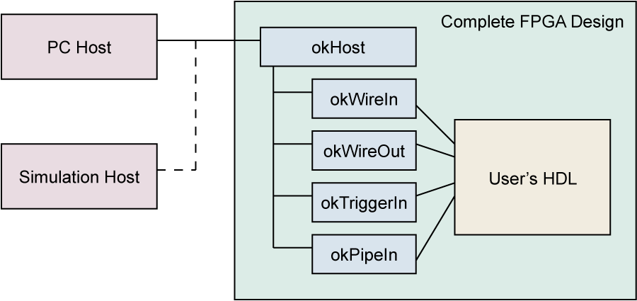
The goal of this type of simulation model is to simulate the complete FPGA design without having to make changes specific to the simulation model. In reality, many designs will require some modification, but in this case the host can be simulated as realistically as possible.
Simulation Requirements
The Opal Kelly FrontPanel Host Simulation Libraries are provided as source HDL to allow for compatibility with a wide range of simulation packages. Examples are provided below for Modelsim and iSim packages packaged with the Xilinx ISE and Altera Quartus toolsets. Verilog and VHDL source is located in the directories under the Simulation subdirectories of the FrontPanel installation location for compilation with the users test fixture.
Limitations
Opal Kelly’s FrontPanel Host Simulation library is for behavioral simulation only. Post place & route simulation is not supported.
Test Fixture Simulation Requirements
A test fixture which simulates the FrontPanel Host requires the following components:
- Instantiation of the device under test (DUT). This is required in any test fixture.
- A behavioral block which calls the Host Simulation Library to mimic the FrontPanel API.
- Inclusion of okHostCalls to simulate the various host API functions.
Verilog: Include okHostCalls.v in the test fixture with ‘include “okHostCalls.v”
VHDL: User must copy indicated code segment from okHostCalls_vhd.txt into the test fixture process.
The last two items are specific to FrontPanel Host Simulation. The table below lists the FrontPanel API calls that are available within the Host Simulation Library. In most cases, the parameters are identical to the corresponding FrontPanel API calls.
| SetWireIns | GetWireOutValue |
| ActivateTriggerIn | IsTriggered |
| WriteToPipeIn | ReadFromPipeOut |
| WriteToBlockPipeIn | ReadFromBlockPipeOut |
| WriteRegister (USB 3.0) | ReadRegister (USB 3.0) |
| UpdateWireIns | UpdateWireOuts |
| UpdateTriggerOuts | FrontPanelReset |
Reset
In a live FPGA design, the FPGA automatically performs a reset of all logic within the fabric after configuration. This assures that the entire design start in a known state which is established by the design.
In a simulation environment, this reset signal is not always simulated and some signals may start in an unknown state. The FrontPanelReset call will reset the host interface functions and assure that the simulation starts off in a known state. It is therefore recommended that your simulation issue a call Reset at the beginning of the simulation.
Simulating Pipes
Pipe transfer calls utilize global array variables in the test fixture to store the data that will be transmitted or received. These global variables must be declared within the user’s testbench if any pipe functionality is to be simulated. In addition, the three parameters BlockDelayStates, ReadyCheckDelay, and PostReadyDelay determine how many clock periods exist between various pipe functions to help simulate possible delays that may occur in actual hardware. BlockDelayStates adds delay between transfers of blocks of data, ReadyCheckDelay simulates a lag in clocks before a Block Pipe module checks for a valid EP_READY signal, and PostReadyDelay simulates a delay after EP_READY is asserted before the next block of data is piped.
An example setup for these requirements is shown here:
parameter BlockDelayStates = 5;  // REQUIRED: # of clocks between blocks of pipe data
parameter ReadyCheckDelay = 5;   // REQUIRED: # of clocks before block transfer before
                                 //    host interface checks for ready (0-255)
parameter PostReadyDelay = 5;    // REQUIRED: # of clocks after ready is asserted and
                                 //    check that the block transfer begins (0-255)
parameter pipeInSize = 16383;    // REQUIRED: byte (must be even) length of default
                                 //    PipeIn; Integer 0-2^32
parameter pipeOutSize = 16383;   // REQUIRED: byte (must be even) length of default
                                 //    PipeOut; Integer 0-2^32
reg   [7:0] pipeIn [0:(pipeInSize-1)];
reg   [7:0] pipeOut [0:(pipeOutSize-1)];Code language: JavaScript (javascript)
After a call to ReadFromPipeOut or ReadFromBlockPipeOut the received data will be in the byte-wide register array pipeOut, arranged as it would be after a call to the C++ method. Similarly, before a call to WriteToPipeIn or WriteToBlockPipeIn the transmitted data should be setup in the byte-wide register array pipeIn. More pipe data arrays may be added as needed by copying and modifying the default pipe functions.
Simulation Sample
A simulation sample is included with FrontPanel to help get you started. The sample include a hypothetical FPGA design with a pseudo-random sequence generator (PRSG) with some parameters under control from the host PC.
Required Files
The following table lists the files required for the simulation along with a brief description.
| FILENAME | DESCRIPTION |
|---|---|
sim.[v|vhd] | This is the source HDL for the simulation example (DUT). |
sim_tf.[v|vhd] | This is the test fixture HDL for the simulation. |
sim.do | This files contains the ModelSim commands to setup, compile, and run the simulation. (Required for Modelsim only) |
sim_isim.bat | This is the iSim batch file to setup, compile, and run the simulation. (Required for iSim only) |
sim_isim.prj | iSim project file. Lists source files for iSim simulation. (Required for iSim only) |
sim_isim.tcl | iSim command script for waveform setup. (Required for iSim only) |
sim_vivado.tcl | Vivado command script for waveform setup. (Required for Vivado only) |
sim_vivado.bat | This is the Vivado batch file to setup, compile, and run the simulation. (Required for iSim only) |
Running the Simulation
- Copy project simulation files above from the FrontPanel installation directory $(FRONTPANEL)/Samples/Simulation/USB[2|3]/[Verilog|VHDL] to a work directory $(WORKDIRECTORY).
- Copy the simulation models from $(FRONTPANEL)/Simulation/USB[2|3]/[Verilog|VHDL] to $WORKDIRECTORY/oksim
Vivado
- Ensure Vivado is in your PATH, and open a command prompt.
- CD to your WORK DIRECTORY:
cd YOUR_WORK_DIRECTORY - Execute the simulation script:
sim_vivado.bat
Modelsim
- Start Modelsim.
- In the Transcript window, CD to your WORK DIRECTORY:
cd YOUR_WORK_DIRECTORY - Execute the simulation script:
do sim.do
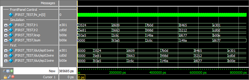
The simulation should run to completion. By selecting the “Wave” window, you should see something like this in Modelsim:
Xilinx ISE iSim
- Open an ISE Design Suite Command Prompt
- CD to your WORK DIRECTORY:
cd YOUR_WORK_DIRECTORY - Execute the simulation script:
sim_isim.bat
Analyzing the Results
The important stimulus from sim_tf.v comes from the statements within the “initial” block and the tasks called from within that block. In sim_tf.vhd, the important stimulus comes from the statements within the main process after “begin” and the procedures outside the okHostCalls section.
The simulated hardware includes a register that can be used either as a standard counter or as a 32-bit Linear Feedback Shift Register (LFSR). The test fixture uses a TriggerIn endpoint to select the mode and WireIns to seed the register with an initial value. It then reads those values using a WireOut endpoint. Note that the values read are not sequential in this portion of the simulation.
When the test fixture sets the hardware register to “piped” mode, it can read sequential values from the LFSR using a PipeOut endpoint. This is because in “piped” mode the register updates only when the pipe is being read, thus avoiding any potential timing issues that arise when the pipe is interrupted by other processes.
In the USB3 version of the test fixture, the okRegisterBridge endpoint is used to interface with block RAM on the simulated FPGA. The values that are read from the block RAM should be the same as the values that are written to the block RAM. Note that in the VHDL simulation, the process will repeat as long as the simulation is actively running. In Verilog, no further stimulus is applied to the signals once the statements in the initial block have been executed.
Simulation Accuracy
Many of the simulated calls to the FrontPanel host occur more quickly than the equivalent calls that are applied to a physical FPGA. The bandwidth constraints on USB and other operating system issues will cause them to happen much slower. In the interest of simulation speed, however, we have accelerated the response time of some of the host simulation actions. The user may, at his or her discretion, place additional delays within the simulation in order to better model the speed of the real host interface. In most cases, this will not be necessary.