Example: Counters
The Counters example is a bit more complicated than the simple example. It includes a few more FrontPanel components and also adds a few Trigger endpoints. More importantly, though, it adds more hardware in the form of HDL so you can see how FrontPanel integrates with HDL in a slightly more complicated setup.
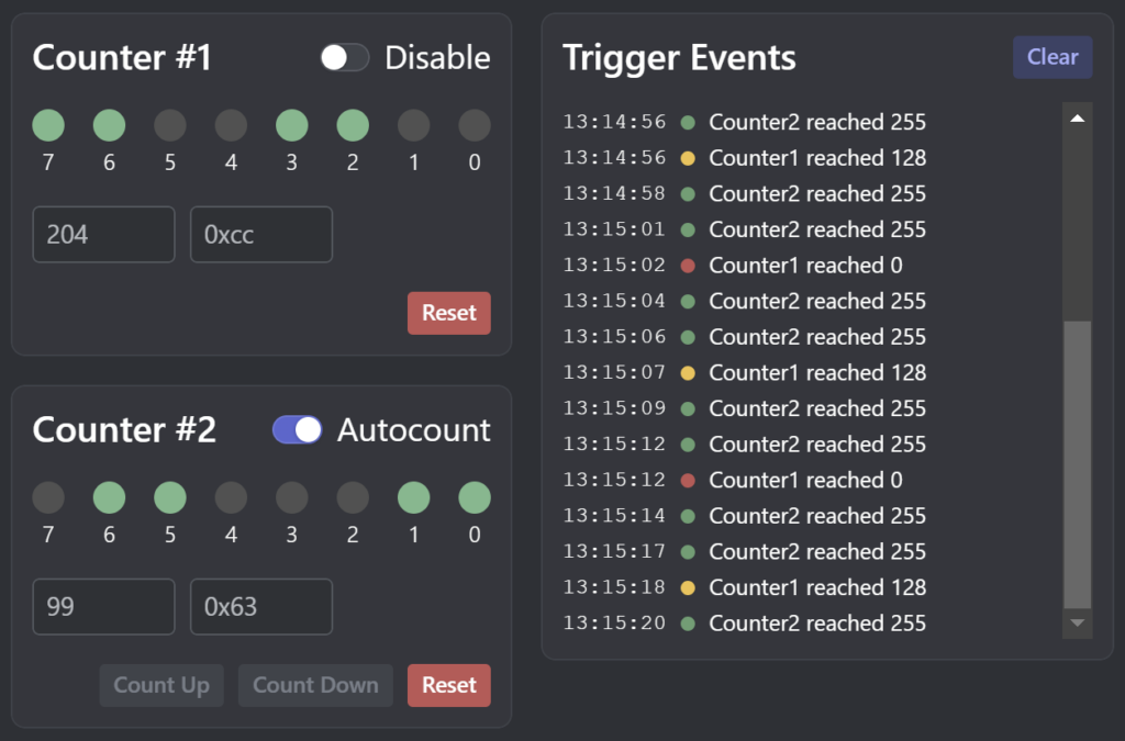
The FrontPanel Platform interface for this example is shown below
Hardware Description
The hardware for the Counters example has two counters, the okHostInterface, a single Wire In endpoint, three Wire Out endpoints, a Trigger In endpoint, and two Trigger Out endpoints. The hardware also routes to the LEDs on the XEM3001.
Counter #1
The first counter is an 8-bit up counter with enable, synchronous reset, disable, and two triggers. The enable signal is generated by a separate 24-bit counter to make the count progression slower. The Verilog HDL for this counter and its clock divider counter is shown here:
always @(posedge sys_clk) begin
   div1 <= div1 - 1;
   if (div1 == 24'h000000) begin
      div1 <= 24'h400000;
      clk1div <= 1'b1;
   end else begin
      clk1div <= 1'b0;
   end

   if (clk1div == 1'b1) begin
      if (reset1 == 1'b1)
         count1 <= 8'h00;
      else if (disable1 == 1'b0)
         count1 <= count1 + 1;
      end

   if (count1 == 8'h00)
      count1eq00 <= 1'b1;
   else
      count1eq00 <= 1'b0;

   if (count1 == 8'h80)
      count1eq80 <= 1'b1;
   else
      count1eq80 <= 1'b0;
endCode language: PHP (php)
From the description, we gather that when RESET1 is asserted, the counter will hold the value 0x00. When DISABLE1 is asserted, the counter holds its current value. Otherwise, the counter will increment each time the clock divider counter expires. We also see that COUNT1EQ00 and COUNT1EQ80 are asserted when the counter is 0x00 or 0x80 respectively.
Note that this counter operates on CLK1 which is mapped to LCLK1 on the PLL.
Counter #2
The second counter operates on CLK2 which is mapped to LCLK2 on the PLL. Using the PLL Configuration Dialog, we will be able to observe the effects of changing the PLL frequencies on the two counters.
The Verilog HDL for this counter and its own divider is listed below. This counter will count up when UP2 is asserted, count down when DOWN2 is asserted, and automatically count up when AUTOCOUNT2 is asserted. Note that UP2 and DOWN2 must be asserted for exactly one CLK2 cycle for the counter to count only one. This is why we have the Trigger endpoints.
always @(posedge sys_clk) begin
   div2 <= div2 - 1;
   if (div2 == 24'h000000) begin
      div2 <= 24'h100000;
      clk2div <= 1'b1;
   end else begin
      clk2div <= 1'b0;
   end

   if (reset2 == 1'b1)
      count2 <= 8'h00;
   else if (up2 == 1'b1)
      count2 <= count2 + 1;
   else if (down2 == 1'b1)
      count2 <= count2 - 1;
   else if ((autocount2 == 1'b1) && (clk2div == 1'b1))
      count2 <= count2 + 1;

   if (count2 == 8'hff)
      count2eqFF <= 1'b1;
   else
      count2eqFF <= 1'b0;
endCode language: PHP (php)
Endpoints
This example uses several endpoints to provide controllable inputs to the hardware and observable outputs to FrontPanel. To reduce the number of endpoints, we have chosen to share them among the counters.
Wire In (0x00)
The only Wire In endpoint is used to carry the RESET1, DISABLE1, and AUTOCOUNT2 signals. These are wires because we want them to have a static state rather than one-shot signals.
| SIGNAL | BIT(S) | DESCRIPTION |
|---|---|---|
| RESET1 | 0 | When asserted, Counter #1 holds the value 0x00 and does not count. |
| DISABLE1 | 1 | When asserted, Counter #2 holds its value and does not count. |
| AUTOCOUNT2 | 2 | Configures counter #2 to autocount. |
| Unused | 15:3 |
Trigger In (0x40)
The only Trigger In endpoint is used for the Counter #2 inputs. These are triggers because we want single events (one-shots) to occur, such as a count-up event.
Note that RESET2 behaves the same as RESET1 but we want to have RESET2 behave as a one-shot event so that the user cannot hold RESET2 asserted. Therefore, we attach this one to a Trigger.
| SIGNAL | BIT(S) | DESCRIPTION |
|---|---|---|
| RESET2 | 0 | When asserted, Counter #2 resets to 0x00 and does not count. |
| UP2 | 1 | When asserted, Counter #2 counts up. |
| DOWN2 | 2 | When asserted. Counter #2 counts down. |
| Unused | 15:3 |
Wire Out (0x20, 0x21, and 0x22)
These wires provide observables for FrontPanel. They are connected as follows:
| ENDPOINT | SIGNAL | DESCRIPTION |
|---|---|---|
| Wire Out 0x20 | COUNT1[7:0] | Counter #1 value. |
| Wire Out 0x21 | COUNT2[7:0] | Counter #2 value. |
| Wire Out 0x22 | BUTTON[3:0] | The lower four bits of this wire bundle contain the status of the on-board pushbuttons. If a button is pressed, the corresponding wire will be asserted. |
Trigger Out (0x60)
This Trigger Out endpoint corresponds to the Counter #1 value. These are triggers because we want these events to update the FrontPanel application.
| SIGNAL | BIT(S) | DESCRIPTION |
|---|---|---|
| COUNT1EQ00 | 0 | When asserted, Counter #1 value is equal to 0x00 |
| COUTN1EQ80 | 1 | When asserted, Counter #1 value is equal to 0x80 |
| Unused | 15:2 |
Trigger Out (0x61)
This Trigger Out endpoint corresponds to the Counter #2 value.
| SIGNAL | BIT(S) | DESCRIPTION |
|---|---|---|
| COUNT2EQFF | 0 | When asserted, Counter #2 value is equal to 0xFF |
| Unused | 15:1 |