PLL Configuration
PLL Configuration (CY22150)
The on-board PLL is available to the USB microcontroller as an I2C peripheral. Through FrontPanel, you can configure the PLL using the PLL Configuration Dialog which is opened by opening Device Settings. When you do so, the current PLL configuration is read and the following dialog appears:
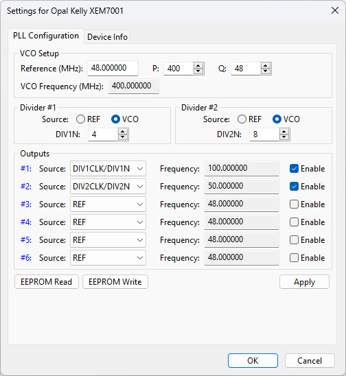
As you make changes in the PLL Configuration Dialog, the output frequencies are automatically updated to indicate how the outputs will behave with the current selections.
Details of the PLL configuration are available in Cypress documentation for the CY22150. A brief description of the parameters follows.
VCO Setup
The CY22150 contains a single PLL which is used as the source to a divider network which then produces the signals at the output. Because of this, all outputs are referenced from the same PLL. The VCO frequency is produced by dividing the reference frequency (fixed at 48 MHz for the XEM3001) by Q and multiplying by P. Cypress specifies that the VCO frequency should be kept between 250 kHz and 400 MHz for reliable operation.
The valid range for P is 8 to 2055. The valid range for Q is 2 to 129.
Divider #1 and #2
Two divide-by-N blocks are available, DIV1N and DIV2N, each with a range from 4 to 127. The source for each divider can either be the VCO or the input reference. The divider outputs are then used to generate the resulting output signal.
Outputs
Each of the six outputs can have a different source, as indicated by the combobox. The choice of this source directly determines the clock frequency for that output. Each output can then be independently enabled or disabled using the checkboxes to the right.
EEPROM Read
The XEM stores the microcontroller bootcode in a small serial EEPROM, which is also used to store a single set of PLL parameters. These parameters are loaded before each FPGA configuration so that valid clock signals are presented to the FPGA when it comes out of configuration.
The PLL Configuration Dialog allows you to read and write this section of EEPROM by using the buttons at the lower left. When you click the button labelled “EEPROM Read,” the stored PLL configuration is read from the EEPROM and the PLL Configuration Dialog is updated to represent these values. The PLL is not re-configured yet. To configure the PLL with these values, you must press “Apply.”
EEPROM Write
The current configuration represented in the PLL Configuration Dialog (not the current PLL configuration) is written to the EEPROM when you press this button. The next time a configuration file is downloaded to the FPGA, this configuration will be loaded into the PLL.
Apply
Any time you change a setting in the PLL Configuration Dialog or load the EEPROM settings, the values change in the dialog, but do not affect the actual PLL on-board. To make the changes take effect, you must press the “Apply” button.
Example PLL Configurations
The table below lists several example frequencies and the PLL settings required to generate that output. If more than one frequency is required for the FPGA, remember that the PLL only has a single VCO, so the outputs must be generated from a single source and (possibly) multiple divider values.
| OUTPUT FREQUENCY | P | Q | VCO FREQUENCY | DIV1N | SOURCE |
|---|---|---|---|---|---|
| 100 MHz | 400 | 48 | 400 MHz | 4 | DIV1CLK/DIV1N |
| 80 MHz | 20 | 4 | 240 MHz | N/A | DIV1CLK/3 |
| 75 MHz | 300 | 48 | 300 MHz | N/A | DIV2CLK/4 |
| 66.66 MHz | 400 | 48 | 400 MHz | 6 | DIV1CLK/DIV1N |
| 50 MHz | 400 | 48 | 400 MHz | 8 | DIV1CLK/DIV1N |
| 15 MHz | 20 | 4 | 240 MHz | 16 | DIV1CLK/DIV1N |
Of course, many other configurations are possible, including those with multiple output frequencies. Please see the specific PLL datasheet for more information.
PLL Configuration (CY22393)
The XEM3010 and XEM3050 products include a Cypress CY22393 PLL, which has a multi-PLL configuration and is therefore more capable than the CY22150. Configuration for the Cypress CY22393 is also available through the FrontPanel API and the FrontPanel Application. Please refer to the Cypress datasheet for parameter details on the CY22393.