System Design
FrontPanel’s main purpose is to move data between your PC and your FPGA in order to provide a convenient and effective way for you to work with the design. FrontPanel was designed to interface simply and easily with new and existing FPGA designs in a way which is powerful enough to apply to a large number of interface methods, yet simple enough to apply to a design in minutes. More importantly, FrontPanel attempts to make the specific implementation of the physical interface (USB or PCI Express, depending on your device) disappear so that those details don’t get in the way of your work.
FrontPanel introduces the concept of “endpoints” to your FPGA design. An endpoint is a bundle of interconnect internal to your design that transports data to or from the PC in some fashion. In many cases, the endpoint can be created from an existing signal in your design which you want to observe in FrontPanel. In other cases, you will create an endpoint to perform a specific data transfer.
When using the FrontPanel Application, “Components” are the corresponding PC-side interface to an endpoint in the FPGA. Components may correspond to a single bit on an endpoint or to several endpoints. For example, an okTriggerButton activates a single bit on a Trigger In endpoint. In contrast, a field that allows you to enter or display a number spanning more than 256 would map to multiple endpoints.
When using the FrontPanel SDK in your own application, the API methods are the corresponding PC-side interface to an endpoint in the FPGA.
Endpoints
In FrontPanel, an endpoint is either a Wire, Trigger, or Pipe, and is either directed in or out of your design. By way of definition, the endpoint will always be labelled from the perspective of the device (FPGA) so an “In” endpoint moves data into the design while an “Out” endpoint moves data out of the design. All of the endpoints in a design are instantiated from Opal Kelly modules and share a common connection to the Host Interface which provides the connection to the PC through the USB or PCIe interface on the XEM board.
The figure below shows the block diagram of an example FPGA design. The okHostInterface is instantiated once and connects to the external FPGA pins as well as a bus shared by all endpoint HDL modules. This bus provides the communications channel for the endpoints to and from the Host Interface.
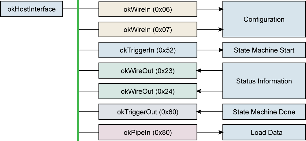
Each instance of an endpoint has an associated address (shown in parentheses) so it may be accessed independent of other endpoints. In this example, two Wire In endpoints setup the configuration for the design and two Wire Out endpoints relay status information back to the PC. The Trigger In endpoint is used to initiate a state machine and a Trigger Out endpoint is used to indicate the completion of the state machine. A Pipe In endpoint is used to load data into a memory within the design.
The three types of endpoints are summarized in the table below and described in more detail after.
| ENDPOINT | SYNC/ASYNC | DESCRIPTION |
|---|---|---|
| Wire In | Asynchronous | Transfers a signal state into the design. (Examples: virtual pushbutton or switch) |
| Wire Out | Asynchronous | Transfers a signal state out of the design. (Examples: virtual LED or hex display) |
| Trigger In | Synchronous | Generates one-shot signal destined for a particular clock. (Example: pushbutton to start a state machine) |
| Trigger Out | Synchronous | Informs the PC that a particular event has occurred. (Example: Done signal from a state-machine pops up a window to the user or starts a data transfer) |
| Pipe In | Synchronous | Multi-byte synchronous transfer into the design. (Example: Memory download, streaming data) |
| Pipe Out | Synchronous | Multi-byte synchronous transfer out of the design. (Example: Memory upload, read results of a computation) |
Wires
A Wire is an asynchronous connection between the PC and an HDL endpoint. A Wire In is an input to the target. A Wire Out is an output from the target.
Wires are designed to fill the position of devices such as LEDs, hexadecimal displays, pushbuttons, DIP switches, and so on. These devices are not synchronous to the design and they usually convey the current state of some internal signal (in the case of Wire Outs).
Wires are updated periodically using a polling mechanism. The rate of update is determined by how fast the PC can poll the FPGA. In FrontPanel, this value is user-configurable. Even at the highest update rate (25 millisecond period), very little bandwidth is consumed, so you should not notice any performance penalty.
Because some FrontPanel components may convey the state of several wires, and in order to avoid multiple transfers over the bus, all wires are captured and updated simultaneously. That is not to say they are synchronous, but that they are all updated at the same time. Therefore, all 64 Wire Ins (or Wire Outs) are transferred together.
Triggers
Triggers are synchronous connections between the PC and an HDL endpoint. A Trigger In is an input to the target. A Trigger Out is an output from the target. Triggers are used to initiate or signal a single event such as the start or end of a state machine.
As an input to the HDL, a Trigger In creates a signal that is asserted for a single clock cycle. The synchronization clock is determined by the user and the HDL module takes care of crossing the clock domains properly.
As an output from the HDL, a Trigger Out triggers the PC when a signal’s rising edge is detected. The “rising edge” is actually determined by the signal’s state from one clock cycle to the next and does not detect glitches. It should be noted that because FrontPanel polls the FPGA periodically, it can only detect independent trigger outs between polls. That is, once a Trigger Out is “set,” it remains set until the next poll clears it.
Pipes
Pipes are synchronous connections between FrontPanel and an HDL endpoint. Unlike Triggers which convey a single event, however, Pipes are designed to transmit a series of bytes to (or from) the endpoint. They are most commonly used to download or upload memory contents but may also be used to stream data to or from the device.
From the HDL point-of-view, a Pipe is always a master. That is, the PC (and therefore the HDL module that implements the Pipe) controls the transaction for both Pipe Ins and Pipe Outs. In addition, the Pipe transactions must be performed at the endpoint’s clock rate (48 MHz for USB devices, 50 or 100 MHz for PCIe devices). To reliably cross this clock boundary, a buffered (FIFO) arrangement is suggested. The Xilinx Core Generator can produce an appropriate FIFO for you.
Although access to the Pipe is always from a slave point of view, use of Triggers provides an effective negotiation method to synchronize the transfer of blocks of data.
Pipe transfer rates will vary depending on host hardware. Our tests indicate transfer rates up to 38 MB/s for USB 2.0 devices, 200 MB/s for PCIe devices, and over 300 MB/s for USB 3.0 devices. For more detail, see Performance Notes below.
Please view our information over at FrontPanel API for using the Pipes API. This page includes clarifying information as well as important length size restrictions that must be followed when using this API. A common error is that the API will return an UnsupportedFeature Error Code if an invalid transfer length is specified.
Block-Throttled Pipes
Block-Throttled Pipes (or BTPipes) are very similar to “standard” Pipes with one important distinction: BTPipes provide a way for the FPGA to “throttle” transfer through the pipe at a block level by asserting back-pressure (also referred to as flow control) against the transfer. The FPGA applies back-pressure to the BTPipe by asserting the EP_READY signal to the USB microcontroller. This allows the FPGA to halt data transfer until data is available or ready to be processed. The back-pressure is only recognized at block-size intervals, thus the term “block-throttled” pipe.
BTPipes provide the same transfer rates as standard pipes, but the throttling allows them to be used in a wider array of applications and can, generally, increase performance by reducing the overhead that would otherwise be required to negotiate the transfer at a higher level.
Block-Throttled Pipes are treated as standard Pipes on PCI Express devices.
Please view our information over at FrontPanel API for using the Block-Throttled Pipes API. This page includes clarifying information, performance recommendations, as well as important block size and length size restrictions that must be followed when using this API. A common error is that the API will return an UnsupportedFeature Error Code if an invalid block size or transfer length is specified.
Registers
The USB 3.0 implementation of FrontPanel includes a “register bridge” that provides an addressable read/write register access point to customer HDL. The interface includes a read strobe and write strobe as well as 32-bit address and 32-bit data ports. This allows the host to access a 16GB addressable register range in the user HDL.
Flow Control and Protocol Design
As you might expect, there are a lot of ways to construct various levels of a communication protocol and a lot depends on the performance, latency, and nature of the data involved. While FrontPanel takes care of a fair bit of the communication puzzle, you should still consider the Wires, Triggers, Registers, and Pipes to be somewhat atomic. This applies most notably in the case of flow control.
Block-Throttled Pipes
FrontPanel has low-level support for flow control with Block Throttled Pipes. But, due to the underlying implementation of USB, this handshaking is not intended to be applied in all situations. It’s there to help reduce induced latency from complex handshaking for transfers that may not be able to fully keep up with the USB bandwidth but “are pretty close”. This means that delays most likely won’t trigger USB or system timeouts.
Block Throttles Pipes rely on handshaking between the USB microcontroller and the FPGA on-board. This is low latency but if things jam up at this level, they can cause USB exceptions which can be messy. You don’t want a BTP stall to cause a USB stall.
When required bandwidth is a smaller fraction of the available USB bandwidth, you’re encouraged to implement additional handshaking using wires or triggers. In this case, the additional overhead of checking a buffer level or threshold through a wire or trigger is minimal with respect to the overall transfer requirements.
Example: Low-Latency Handshaking
Let’s call the USB available bandwidth about 300 MB/s. This means that, in your system, the maximum transfer rate of a large block of bulk data over USB is around 300 MB/s.
You need to transport 200 MB/s of data streaming from a data acquisition device like an ADC or image sensor. In this case, you don’t have a ton of overhead with which to support routine wire/trigger checks for handshaking. Here, it makes sense to lean on the Block Throttled Pipe and the handshaking available at the firmware / FPGA level. Due to the streaming data source, your data is more or less guaranteed to be there consistently so your transfers are not likely to timeout.
This is a low-latency handshaking configuration where the firmware and FPGA handle all aspects of handshaking before the data is transported to the host and reaches your software. Any significant stalls here may terminate the transfer with a timeout. This is an undesirable situation that should be avoided.
Example: High-Latency Handshaking
You need to transport 75 MB/s but it arrives in big packets with some time between them. In this case, you have plenty of overhead available and can implement a polled wire/trigger check for handshaking. Once your handshaking requirement is met, you can probably use regular pipes (with adequate buffering on the FPGA side to avoid any FIFO exceptions) or BTP, as required, if your data and buffering still require some low-latency handshaking.
This is a higher-latency example than the one above. The transfers can perform at high speed, but because there is a period of no data, your application has an opportunity to perform polling to discover when the next packet of data is available. This polling can help you prevent the undesirable timeout condition because you only initiate a transfer when you are confident that the transfer can proceed to completion without significant delay.
This approach is the one taken in our Camera Reference Design. Here, images are captured to a frame buffer. The host application polls the gateway to determine when one (or more) images are available in the frame buffer. If there is data available, the application performs a read to capture this data without delay.
Timeout
In the context of protocol design and hardware interfaces, a timeout is a predefined period of time when the system will wait for an action or response before it proceeds. It is used to prevent the process from blocking forever or taking too long to complete a task. In some cases, this is considered an error condition. In other cases, it is used to provide the user or the system an opportunity to interrupt or cancel the task for some higher priority.
This is a good opportunity to distinguish between the implications of timeouts within a system. Consider this abridged set:
- The FrontPanel API may make a request of the underlying host operating system, hardware, or driver that may timeout.
- An application’s request to the FrontPanel API may timeout because of resource limits exposed by the request.
- The application’s request itself may timeout to the user because of resources limits on the hardware platform.
It is generally the responsibility the next higher layer to understand the resource limits and behavior of the lower level and then communicate any error or timeout conditions to the next layer appropriately.
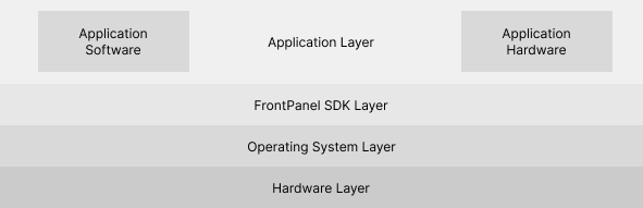
Application Layer
The application layer is where the application software and application hardware reside. The application software utilizes the FrontPanel API to communicate with the FrontPanel Firmware on the FPGA device that constitutes the application hardware. The use of timeout and the appropriate handling is entirely up to the system designer. There are some applications that would never need to design for or support a timeout at this level. Likewise, there are some applications that would expect to experience a timeout at this level. For example, consider an application that continually reads periodic data from a remote device over a radio link. If that link fails, the absence of signal would result in a non-responsive link and what could be considered a timeout condition to the user.
There is nothing about the FrontPanel system design that prevents an engineer from incorporating timeout at the application layer.
Operating System and Hardware Layers
Practically speaking, a timeout at the operating system and hardware layer is generally considered an error condition and should not happen in the normal course of events. It is often the case that data may be lost if a timeout occurs here and that some level of reset negotiation may need to occur. More importantly, however, timeout support and behavior is not universal across all hardware or operating system implementations. The layer above treats these events as exceptions with appropriate exception handling. A good user experience is not always preserved.
FrontPanel SDK Layer
Some FrontPanel API methods are able to respond with a timeout should one occur at the operating system and hardware layers. These are considered exceptions. The FrontPanel firmware may be in an inconsistent state after such an exception. Data may be lost.
The notable consideration at this layer is that the application hardware may introduce a situation that can cause an exception at this layer and we discourage this practice.
For example, the Block-Throttled Pipes have a READY signal that may be deasserted to force the firmware to pause an active data transfer to the host. If this condition persists, a timeout may be passed to the FrontPanel SDK layer. The intent of this capability was to allow the hardware to moderate transmission rates near the maximum transfer rate supported by the interface so that more expensive handshaking could be eliminated.
Heavy-handed use of the READY throttle, however, should not be relied upon. If this level of throttling is required, then the system is certainly tolerant of the more imposing handshaking that could be implemented with wires and triggers. This is the approach recommended.
Block-Throttled Pipes (USB 3.0)
In most cases, when the device, host, and other components are all operating correctly, you should never see a timeout occur. Block-throttled pipes (BTPipes) offer an opportunity for the device to assert back-pressure on a transfer. This back-pressure is applied at a fairly low level, offering a compromise between high performance and low latency in response to the back-pressure. It is possible, however, that back-pressure can be applied long enough to induce a timeout. Because this is implemented at a low level, this can cause data loss, data corruption, or loss of synchronization with the device.
Back-pressure should be applied judiciously and only to slow the transfer of data temporarily. If you need to slow the transfer more significantly, we suggest using an implementation at a higher level such as one invoking the use of Wire and Trigger endpoints to negotiate a block transfer prior to initiating the Pipe call. This approach assures that the transfer completes well within the timeout window.
Components
Components represent the other half of the interface, each connecting to an appropriate endpoint or multiple endpoints within the design. Most components have a graphical representation within FrontPanel such as a pushbutton, virtual LED, or numerical display. Some components, however, are hidden from view. An example of a hidden component would be one that makes a sound in response to a Trigger Out.