USB 3.0 HDL
FPGA Resource Requirements
The FrontPanel-enabling modules have been designed to consume as few resources as possible within the FPGA. The resource requirements for each block are listed in the tables below. Keep in mind that these are requirements for an endpoint with all bits used. In many cases, the place and route tools will optimize and remove unused components.
| RESOURCE | SLICE FFS | 4-IN LUTS | BLOCK RAMS |
|---|---|---|---|
| Host Interface | 33 | 49 | 0 |
| Wire In | 16 | 14 | 0 |
| Wire Out | 8 | 5 | 0 |
| Trigger In | 32 | 21 | 0 |
| Trigger Out | 27 | 15 | 0 |
| Pipe In | 9 | 10 | 0 |
| Pipe Out | 0 | 6 | 0 |
| BT Pipe In | ? | ? | ? |
| BT Pipe Out | ? | ? | ? |
| Register Bridge | ? | ? | ? |
Wire-OR
Multiple endpoints are attached to the okHE bus on the okHost by using a Wire-OR. Each endpoint is told when it can assert its data on the bus. At all other times, it drives 0. The Wire-OR component performs a bitwise OR operation on each bit of the bus and outputs the result. In this manner, multiple endpoints can share a bus without requiring the use of tristates or a large mux.
The okWireOR is provided as a parameterized helper module in okLibrary.v and okLibrary.vhd. Please refer to the provided samples to see how to instantiate this module.
The Host Interface
The host interface is the gateway for FrontPanel to control and observe your design. It contains the logic that lets the USB microcontroller on the device communicate with the various endpoints within the design. Exactly one host interface must be instantiated in any design which uses the FrontPanel components.
The Host Interface component is the only block which is synthesized with your design. It contains a Host Interface core component (provided as a pre-synthesized module) as well as the necessary IOB components to connect to the host interface pins of the FPGA.
The diagram below illustrates the structural relationships between the various endpoints, the okWireOR, and okHost modules.
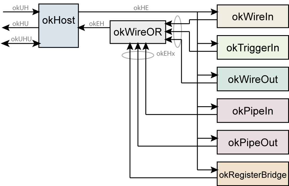
okHost
This module must be instantiated in any design that makes use of FrontPanel virtual interface components. The following signals need to be connected directly to pins on the FPGA which go to the USB microcontroller on the device. For a listing of the pin locations for a particular product, please see the user’s manual for that device.
| SIGNAL | DIRECTION | DESCRIPTION |
|---|---|---|
okUH[4:0] | Input | Host interface input signals. |
okHU[2:0] | Output | Host interface output signals. |
okUHU[31:0] | In/Out | Host interface bidirectional signals. |
okAA | In/Out | Host interface bidirectional signal |
The remaining ports of the okHost are connected to a shared bus inside your design. These signals are collectively referred to as the target interface bus. Each endpoint must connect to these signals for proper operation.
| SIGNAL | DIRECTION | DESCRIPTION |
|---|---|---|
okHE[112:0] | Output | Control signals to the target endpoints. |
okEH[64:0] | Input | Control signals from the target endpoints. |
okClk | Output | Buffered copy of the host interface clock (100.8 MHz). |
Instantiation of the okHost is simple in either VHDL or Verilog. Use the templates below in your toplevel HDL design. A more detailed listing can be found later in this manual as one of the examples.VERILOG INSTANTIATION
okHost okHI (.okUH(okUH), .okHU(okHU), .okUHU(okUHU), .okAA(okAA),.okClk(okClk), .okHE(okHE), .okEH(okEH));Code language: CSS (css)VHDL INSTANTIATION
okHI : okHost port map (okUH => okUH, okHU => okHU, okUHU =>okUHU, okAA => okAA,okClk => okClk, okHE => okHE, okEH => okEH);Code language: PHP (php)Each endpoint is connected to 48 target interface pins on the okHost module. The direction is from the perspective of the endpoint module.
| SIGNAL | DIRECTION | DESCRIPTION |
|---|---|---|
okHE[112:0] | Input | Interface control (host to endpoint) |
okEH[64:0] | Output | Interface control (endpoint to host) |
These signals are present in every endpoint. In the signal tables for the independent endpoints below, we have left out these common signals.
DNA Ports
okHost instantiates the device’s only DNA_PORT and makes its output available. The following are additional ports of okHost for your optional use.
| SIGNAL | DIRECTION | DESCRIPTION |
|---|---|---|
dna[56:0] (7-Series)dna[95:0] (UltraScale) | Output | Device’s unique DNA value. |
dna_valid | Output | dna bus is valid. |
Wire In
In addition to the target interface pins, the okWireIn adds a single 32-bit output bus called EP_DATAOUT[31:0]. The pins of this bus are connected to your design as wires and act as asynchronous connections from FrontPanel components to your HDL.
When FrontPanel updates the Wire Ins, it writes new values to the wires, then updates them all at the same time. Therefore, although the wires are asynchronous endpoints, they are all updated at the same time on the host interface clock.
| SIGNAL | DIRECTION | DESCRIPTION |
|---|---|---|
EP_DATAOUT[31:0] | Output | Wire values output. (sent from host) |
VERILOG INSTANTIATION
okWireIn wire03 (.okHE(okHE),.ep_addr(8'h03), .ep_dataout(ep03data));VHDL INSTANTIATION
wire03 : okWireIn port map (okHE => okHE,ep_addr => x"03", ep_dataout => ep03data);Code language: PHP (php)Wire Out
An okWireOut module adds a single 32-bit input bus called EP_DATAIN. Signals on these pins are read whenever FrontPanel updates the state of its wire values. In fact, all wires are captured simultaneously (synchronous to the host interface clock) and read out sequentially.
| SIGNAL | DIRECTION | DESCRIPTION |
|---|---|---|
EP_DATAIN[31:0] | Input | Wire values input. (to be sent to host) |
VERILOG INSTANTIATION
okWireOut wire21 (.okHE(okHE), .okEH(okEH),.ep_addr(8'h21), .ep_datain(ep21data));VHDL INSTANTIATION
wire21 : okWireOut port map (okHE => okHE, okEH => okEH,ep_addr => x"21", ep_datain => ep21data);Code language: PHP (php)Trigger In
The okTriggerIn provides EP_CLK and EP_TRIGGER as interface signals. The Trigger In endpoint produces a single-cycle trigger pulse on any of EP_TRIGGER which is synchronized to the clock signal EP_CLK. Therefore, the single-cycle does not necessarily have to be a single host interface cycle. Rather, the module takes care of crossing the clock boundary properly.
| SIGNAL | DIRECTION | DESCRIPTION |
|---|---|---|
EP_ADDR[7:0] | Input | Endpoint address. |
EP_CLK | Input | Clock to which the trigger should synchronize. |
EP_TRIGGER[31:0] | Output | Independent triggers from host. |
VERILOG INSTANTIATION
okTriggerIn trigIn53 (.okHE(okHE),.ep_addr(8'h53), .ep_clk(clk2), .ep_trigger(ep53trig));VHDL INSTANTIATION
trigIn53 : okTriggerIn port map (okHE => okHE,ep_addr => x"53", ep_clk => clk2, ep_trigger => ep53trig);Code language: PHP (php)Trigger Out
The target may trigger the host using this module. EP_TRIGGER[31:0] contains 32 independent trigger signals which are monitored with respect to EP_CLK. If EP_TRIGGER[x] is asserted for the rising edge of EP_CLK, then that trigger will be set. The next time the host checks trigger values, the triggers will be cleared.
| SIGNAL | DIRECTION | DESCRIPTION |
|---|---|---|
EP_ADDR[7:0] | Input | Endpoint address. |
EP_CLK | Input | Clock to which the trigger is synchronized. |
EP_TRIGGER[31:0] | Input | Independent triggers to host. |
VERILOG INSTANTIATION
okTriggerOut trigOut6A (.okHE(okHE), .okEH(okEH),.ep_addr(8'h6a), .ep_clk(clk2), .ep_trigger(ep6Atrig));VHDL INSTANTIATION
trigOut6A : okTriggerOut port map (okHE => okHE, okEH => okEH,ep_addr => x"6a", ep_clk => clk2, ep_trigger => ep6Atrig);Code language: PHP (php)Pipe In
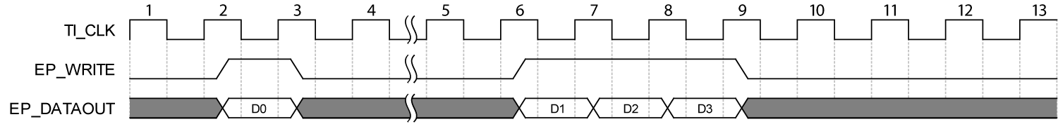
The okPipeIn module provides a way to move synchronous multi-byte data from the host to the target. As usual, the host is the master and therefore the target must accept data as it is moved through this pipe (up to 100.8 MHz). The EP_WRITE signal is an active high signal which is asserted when data is to be accepted by the target on EP_DATAOUT[31:0]. It is possible that EP_WRITE be asserted for several consecutive cycles without deasserting. In such a case, EP_DATAOUT[31:0] will be changing every clock.
This somewhat simple Pipe In implementation requires that the target interface be very responsive to incoming pipe data. If the target is able to keep up with the throughput, but needs to handle data in a block fashion, coupling the okPipeIn with a FIFO (from the Xilinx CORE generator) is a good solution. Alternatively, an okBTPipeIn can be used.
The timing diagram below indicates how data is presented by the okPipeIn to user HDL. EP_DATAOUT contains valid data for any clock cycle where EP_WRITE is asserted during the rising edge of TI_CLK. Note that the transfer sends 4 words in this example. Although contrived, it is important to note that EP_WRITE may deassert during the transfer. This will generally happen with longer transfers (>256 words).
| SIGNAL | DIRECTION | DESCRIPTION |
|---|---|---|
EP_ADDR[7:0] | Input | Endpoint address. |
EP_DATAOUT[31:0] | Output | Pipe data output. |
EP_WRITE | Output | Active high write signal. Data should be captured when this signal is asserted. |
VERILOG INSTANTIATION
okPipeIn pipeIn9C (.okHE(okHE), .okEH(okEH),.ep_addr(8'h9c), .ep_dataout(ep9Cpipe), .ep_write(ep9Cwrite));VHDL INSTANTIATION
pipeIn9C : okPipeIn port map (okHE => okHE, okEH => okEH,ep_addr => x"9c", ep_dataout => ep9Cpipe, ep_write => ep9Cwrite);Code language: PHP (php)Pipe Out
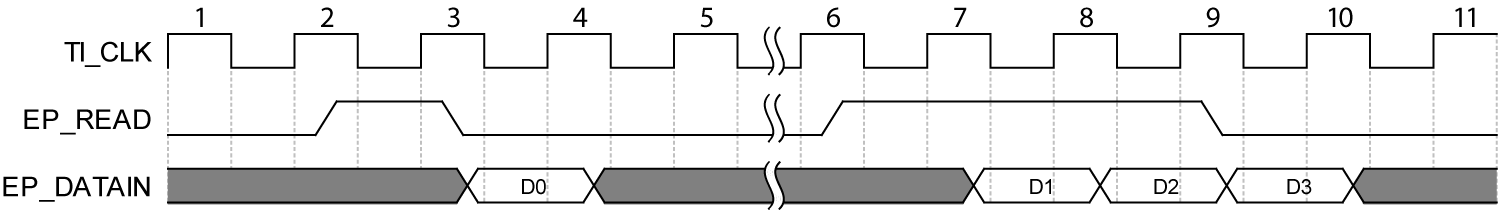
The okPipeOut module implements a simple version of the Pipe Out endpoint to move synchronous multi-byte data from the target to the host. Because the host is master, all reads (on the target side) occur at the host’s whim. Therefore, data must be provided whenever EP_READ is asserted.
This simple implementation of a Pipe Out endpoint requires that the target interface be somewhat responsive to host read requests. If the target is able to keep up with the throughput, but needs to handle data in a block fashion, coupling the okPipeOut with a FIFO (from the Xilinx CORE generator) is a good solution. Alternatively, an okBTPipeOut can be used.
The timing diagram below indicates how the user HDL needs to respond to EP_READ with EP_DATAIN valid data. When EP_READ is asserted for the rising edge of TI_CLK, user HDL must respond with valid EP_DATAIN on the next clock edge, subject to setup and hold times appropriate for (TAS and TAH in the FPGA CLB timing documentation). Of course, these times are also subject to the particular routing and logic in your HDL implementation. Note that the transfer sends 4 words in this example. Although contrived, it is important to note that EP_READ may deassert during the transfer. This will generally happen with longer transfers (>256 words).
| SIGNAL | DIRECTION | DESCRIPTION |
|---|---|---|
EP_ADDR[7:0] | Input | Endpoint address. |
EP_DATAIN[31:0] | Input | Pipe data input. |
EP_READ | Output | Active-high read signal. Data must be provided in the cycle following as assertion of this signal. |
VERILOG INSTANTIATION
okPipeOut pipeOutA3 (.okHE(okHE), .okEH(okEH),.ep_addr(8'ha3), .ep_datain(epA3pipe), .ep_read(epA3read));VHDL INSTANTIATION
pipeOutA3 : okPipeOut port map (okHE => okHE, okEH => okEH,ep_addr => x"a3", ep_datain => epA3pipe, ep_read => epA3read);Code language: PHP (php)Block-Throttled Pipe In
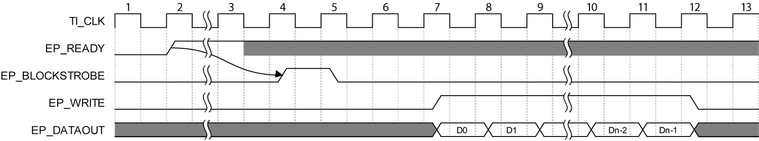
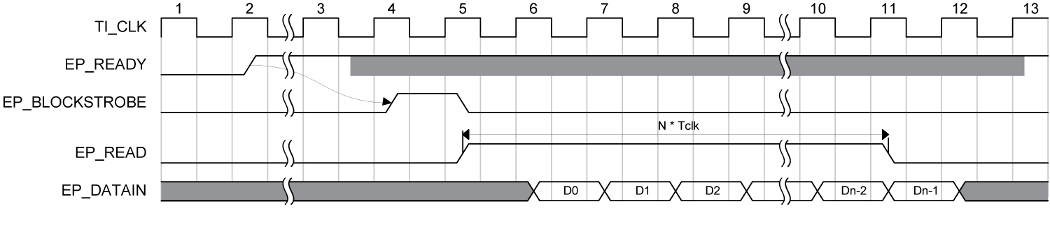
The Block-Throttled Pipe In module is similar to the okPipeIn module, but adds two signals, EP_BLOCKSTROBE and EP_READY, to handle block-level negotiation for data transfer. The host is still master, but the FPGA controls EP_READY. When EP_READY is asserted, the host is free to transmit a full block of data. When EP_READY is deasserted, the host will not transmit to the module.
EP_READY could, for example, be tied to a level indicator on a FIFO. When the FIFO has a full block of space available, it will assert EP_READY signifying that it can accept a full block transfer.
Software timeout may occur if the requested transfer does not complete within the timeout period. It is best practice to avoid a timeout condition with proper protocol design appropriate to the application. See Handshaking and Protocol Design for design recommendations.
| SIGNAL | DIRECTION | DESCRIPTION |
|---|---|---|
EP_ADDR[7:0] | Input | Endpoint address. |
EP_DATAOUT[31:0] | Output | Pipe data output. |
EP_WRITE | Output | Active-high write signal. Data should be captured when this signal is asserted. |
EP_BLOCKSTROBE | Output | Active-high block strobe. This is asserted for one cycle just before a block of data is written. |
EP_READY | Input | Active-high ready signal. Logic should assert this signal when it is prepared to receive a full block of data. |
VERILOG INSTANTIATION
okBTPipeIn pipeIn9C (.okHE(okHE), .okEH(okEH),.ep_addr(8'h9c), .ep_dataout(ep9Cpipe), .ep_write(ep9Cwrite),.ep_blockstrobe(ep9Cstrobe), .ep_ready(ep9cready));VHDL INSTANTIATION
pipeIn9C : okBTPipeIn port map (okHE => okHE, okEH => okEH,ep_addr => x"9c", ep_dataout => ep9Cpipe, ep_write => ep9Cwrite,ep_blockstrobe => ep9Cstrobe, ep_ready => ep9cready);Code language: PHP (php)Block-Throttled Pipe Out
The Block-Throttled Pipe Out module is similar to the okPipeOut module, but adds two signals, EP_BLOCKSTROBE and EP_READY to handle block-level negotiation for data transfer. The host is still master, but the FPGA controls EP_READY. When EP_READY is asserted, the host is free to read a full block of data. When EP_READY is deasserted, the host will not read from the module.
EP_READY could, for example, be tied to a level indicator on a FIFO. When the FIFO has a full block of data available, it will assert EP_READY signifying that a full block may be read from the FIFO.
It is best practice to avoid a timeout condition with proper protocol design appropriate to the application. See Handshaking and Protocol Design for design recommendations.
| SIGNAL | DIRECTION | DESCRIPTION |
|---|---|---|
EP_ADDR[7:0] | Input | Endpoint address. |
EP_DATAIN[31:0] | Input | Pipe data input. |
EP_READ | Output | Active-high read signal. Data must be provided in the cycle following the assertion of this signal. |
EP_BLOCKSTROBE | Output | Active-high block strobe. This is asserted for one cycle just before a block of data is read. |
EP_READY | Input | Active-high ready signal. Logic should assert this signal when it is prepared to transmit a full block of data. |
VERILOG INSTANTIATION
okBTPipeOut pipeOutA3 (.okHE(okHE), .okEH(okEH),.ep_addr(8'ha3), .ep_datain(epA3pipe), .ep_read(epA3read),.ep_blockstrobe(epA3strobe), .ep_ready(epA3ready));VHDL INSTANTIATION
pipeOutA3 : okBTPipeOut port map (okHE => okHE, okEH => okEH,ep_addr => x"a3", ep_datain => epA3pipe, ep_read => epA3read,ep_blockstrobe => epA3strobe, ep_ready => epA3ready);Code language: PHP (php)Register Bridge
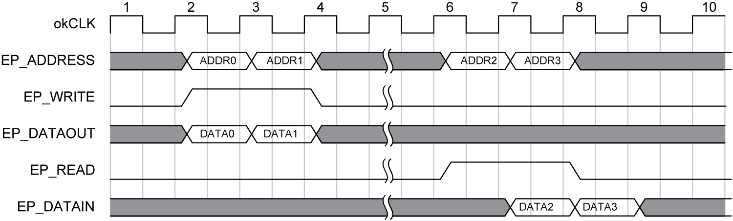
The Register Bridge provides synchronous register file access to a 32-bit data, 32-bit address register space. User HDL is responsible for responding to register reads and writes, but is free to interpret the address in any manner.
Register Writes
A register write is signalled with the one-cycle assertion of EP_WRITE. When EP_WRITE is asserted, user HDL should capture both the address (on EP_ADDRESS) and data (on EP_DATAOUT). Register writes may occur to any address in any clock cycle, including multiple consecutive cycles.
Register Reads
A register read is signalled with the one-cycle assertion of EP_READ. When EP_READ is asserted, user HDL should capture the address (EP_ADDRESS) and respond in the next clock cycle by driving EP_DATAIN with the value requested. Register reads may be requested for any address in any clock cycle, including multiple consecutive cycles.
| SIGNAL | DIRECTION | DESCRIPTION |
|---|---|---|
EP_WRITE | Output | Asserted during a write cycle. |
EP_READ | Output | Asserted during a read cycle. |
EP_ADDRESS[31:0] | Output | Driven with the requested address during read and write cycles. |
EP_DATAOUT[31:0] | Output | Driven with valid data during a write cycle. |
EP_DATAIN[31:0] | Input | This value is captured in the cycle following a read cycle. |
VERILOG INSTANTIATION
okRegisterBridge regBridge (.okHE(okHE), .okEH(okEH),.ep_write(regWrite), .ep_read(regRead), .ep_address(regAddress),.ep_dataout(regDataOut), .ep_datain(regDataIn));Code language: CSS (css)VHDL INSTANTIATION
regBridge : okRegisterBridge port map (okHE => okHE, okEH => okEH,ep_write => regWrite, ep_read => regRead, ep_address => regAddress,ep_dataout => regDataOut, ep_datain => regDataIn);Code language: PHP (php)