Flash Programming Tool

FrontPanel is able to program the on-board Flash memory for supported devices. The typical application for Flash programming is downloading an FPGA configuration bitfile to the Flash to allow the device to boot the FPGA on power-up in a “non-tethered” application. The host interface may be used after boot, if required.
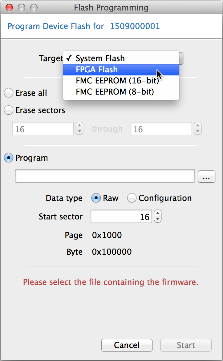
On-board Flash memory is classified as one of three types:
- System Flash is available to the host controller and may be accessed without an active FPGA configuration. This memory may not be accessed directly by the FPGA. System Flash is only available on USB 3.0 devices.
- FPGA Flash is connected to the FPGA. It is accessible only to the host through the use of an FPGA configuration that supports communication between the host and the memory.
- FMC EEPROM is optionally available on the carrier board. An IPMI configuration can be stored there to automatically configure the adjustable voltage rails to be compatible with the carrier I/O levels.
System Flash Programming
This option is only available for USB 3.0 devices. USB 2.0 devices do not have a System Flash.
FrontPanel uses the FlashErase, FlashWrite, and FlashRead APIs to erase and program the System Flash memory, if available. Please see the corresponding Device User’s Manual for available size and memory layout information which is also available via the DeviceInfo API structure.
If you are transferring a configuration file (Xilinx .bit file or Altera .rbf file), and intend to have the device load that configuration file when powered on, select “Configuration” as the data type. This will also setup the Reset Profile so that the firmware will load the configuration.
FPGA Flash Programming
Programming the FPGA Flash requires FrontPanel to configure the FPGA with a special bitfile that allows FrontPanel to access the Flash memory. This bitfile is first downloaded to the FPGA before the Flash erase or programming steps are performed.
Power on configurations can be loaded into the FPGA Flash to be run automatically.
FMC (IPMI) EEPROM Programming
Some Opal Kelly modules have adjustable I/O voltage rails that can be configured with settings in an EEPROM on the carrier board. These settings are stored in the IPMI format. Web tools are provided for generating IPMI configurations for supported modules. Those configurations can be loaded onto a carriers IPMI EEPROM using the FrontPanel applications Flash Programming tool. Select the FMC EEPROM option as the target, choose the generated IPMI binary file, and click Start. The 16-bit and 8-bit options are for generated IPMI files that use 16-bit or 8-bit addressing. The addressing depends on the EEPROM size selection in the generation web tool.