Example: Ethernet Design
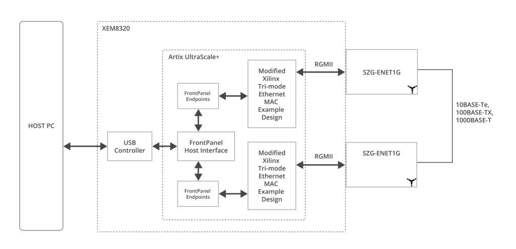
This example design allows you to use two SZG-ENET1Gs for communication between them, or you can use a single SZG-ENET1G by enabling the internal PHY loopback test mode.
Sources
We have modified AMD’s Tri-Mode Ethernet MAC Vivado IP Core example design to be compatible with the XEM8320 with SZG-ENET1G. Please read each section below for more information.
AMD Tri-Mode Ethernet MAC Example Design
AMD’s Tri-Mode Ethernet MAC Vivado IP Core example design was initially created for the KC705 and AC701 boards. You can find the documentation for this design at the following link. However, the source code itself is not available at that link. To access the source code, you need to generate it from AMD’s Tri-Mode Ethernet Vivado IP core within Vivado. AMD’s example design sources can be generated freely without requiring an IP Core license.
Modified Source Code: XEM8320 with SZG-ENET1G Compatibility
Our team has made modifications to AMD’s Tri-Mode Ethernet MAC Vivado IP core example design to make it compatible with the XEM8320 and SZG-ENET1G. To facilitate the identification of modifications, we recommend obtaining a copy of AMD’s example design listed above. This will allow you to perform diffs between their original source code and our modified version. Additionally, we have included code comments that begin with // Opal Kelly to further highlight our specific modifications and additions.
These modifications include replacing the KC705/AC701’s physical interfaces (DIP switches, pushbuttons, and LEDs) with FrontPanel virtual interface components. The AMD Example Design PHY configuration state machine has been modified to configure the TI DP83867 PHY on the SZG-ENET1G peripheral. The original configuration for the PHY on the KC705 or AC701 boards is similar, but there are subtle differences between these PHYs that render the original configuration incompatible. We have also enhanced their base design with additional capabilities, including the ability to configure destination and source MAC addresses, introduce errors in the transmission, and track the number of packets sent and received.
You can access the example design source code on our Opal Kelly Open-Source GitHub Repository: Ethernet Example Design
Requirements
- Hardware
- XEM8320
- SZG-ENET1G
Two are needed to communicate between SYZYGY port A and port C
Or, one SZG-ENET1G to use the example design in internal PHY loopback test mode on either port A or port C - Ethernet cable if communicating between two SZG-ENET1Gs
- Pre-built bitfile
- Software
Two applications are provided as options for interfacing with the design
Tutorials
Operate Single SZG-ENET1G
This tutorial will guide you through using a single SZG-ENET1G with this example design. You will accomplish placing your SZG-ENET1G into internal PHY loopback mode and then generating and receiving/checking packets.
- Download and install FrontPanel SDK version 5.2.5 or later. Version 5.2.5 adds support for the XEM8320.
- Turn off your XEM8320.
- Plug a SZG-ENET1G into port A on your XEM8320.
- Connect your XEM8320 to your host PC with the provided USB cable.
- Power on your XEM8320.
- Open the FrontPanel application on your host PC.
- Configure your XEM8320 with the pre-built bitfile using the FrontPanel application.
- Load the corresponding XFP or FrontPanel Alloy application profile.
- XFP – Load the
EthernetExampleDesign.xfpXML file. - FrontPanel Alloy – Load the
index.htmlfile contained in theEthernetExampleDesign-v1.1.AlloyApplication.zip.
- XFP – Load the
- Follow the instructions below in the “How To” section for “Place PHY in internal loopback mode and generate and check data on the same port.”
Operate using two SZG-ENET1Gs
This tutorial will guide you through using two SZG-ENET1Gs with this example design. You will accomplish generating and receiving/checking packets between two SZG-ENET1Gs.
- Download and install FrontPanel SDK version 5.2.5 or later. Version 5.2.5 adds support for the XEM8320.
- Turn off your XEM8320.
- Plug a SZG-ENET1G into port A on your XEM8320.
- Plug a SZG-ENET1G into port C on your XEM8320.
- Connect both SZG-ENET1Gs together using an Ethernet cable.
- Connect your XEM8320 to your host PC with the provided USB cable.
- Power on your XEM8320.
- Open the FrontPanel application on your host PC.
- Configure your XEM8320 with the pre-built bitfile using the FrontPanel application.
- Launch the FrontPanel application and load the corresponding XFP or FrontPanel Alloy application profile.
- XFP – Load the
EthernetExampleDesign.xfpXML file. - FrontPanel Alloy – Load the
index.htmlfile contained in theEthernetExampleDesign-v1.1.AlloyApplication.zip.
- XFP – Load the
- Follow the instructions below in the “How To” section for “Update MAC addresses and speed of communication between two SZG-ENET1Gs”
- Follow the instructions below in the “How To” section for “Generate data in one port and check that data on the other port”
- Follow the instructions below in the “How To” section for “Generate and check data in the same port and use the other port in HDL loopback mode”
- Experiment with some of the GUI settings listed in the “FrontPanel User Interface Reference” section.
Building the Gateware
A valid license for the AMD Tri-Mode Ethernet Media Access Controller (TEMAC) IP is required if you wish to build the project. You can request an evaluation license through the AMD website. The pre-built bitfile was built using this evaluation license.
- Acquire the sources for the Ethernet Example design on GitHub.
- Open Vivado GUI.
- Within the TCL console
cdto thedesign-resources/ExampleProjects/EthernetExampleDesign/directory containingproject.tcl. - Run
source project.tcl - Import FrontPanel HDL for your product into the project. These sources are located within the FrontPanel SDK installation.
- Generate Bitstream.
FrontPanel User Interface Reference
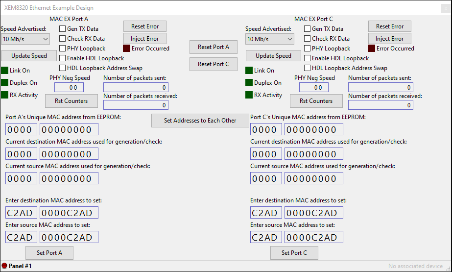
XFP User Interface
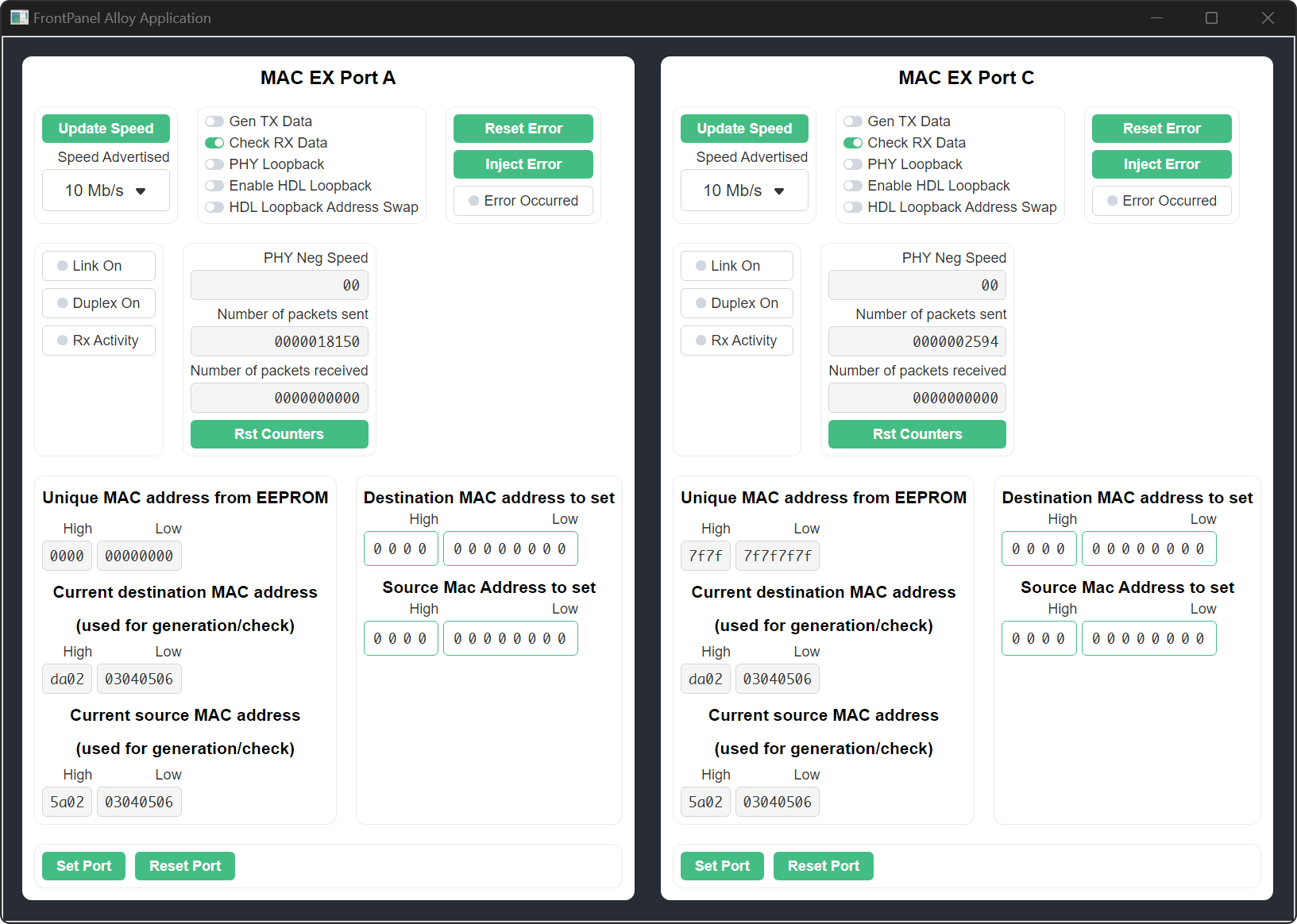
FrontPanel Alloy User Interface
KEY
Updating speed
- Speed Advertised: Speed to advertise for auto-negotiation.
- Update Speed: Update the speed selected for auto-negotiation and restart auto-negotiation.
Observation
- Link On LED: Link established indicator from the PHY.
- Duplex On LED: Duplex enabled indicator from the PHY.
- RX Activity: Blink speed is relative to the speed of received packets.
- Phy Neg Speed: Indicates the speed at which the PHY successfully negotiated the link. 00 = 10Mb/s, 01 = 100Mb/s, and 10 = 1000Mb/s
Controllability
- Gen TX Data: Generate output data from this port at incrementing lengths.
- Check RX Data: Check received generated data length.
- PHY Loopback: Put the PHY in internal loopback mode. (Digital Loopback Mode)
- Enable HDL Loopback: Send RX data back out onto the TX.
- HDL Loopback Address Swap – When in HDL loopback mode this swaps the destination and source address before sending the data to the TX. This mode should be used when using an Ethernet protocol tester.
Error
- Error Occurred LED: Indicates that an error has occurred when checking the TX generated data that is received. This LED is sticky and must be reset.
- Reset Error: Reset the sticky Error Occurred LED.
- Inject Error: Injecting an error forces the generating data to not increment in length.
MAC address
- Unique MAC address from EEPROM: This is the value of the unique MAC address for this SZG-ENET1G. This value is stored in the EEPROM device Pre-Programmed with a EUI-48™ MAC Address that has been assigned by the IEEE Registration Authority.
- Set Port: This sets the destination and source address that was entered into the corresponding text box entries.
- Set Addresses to Each Other: When two SZG-ENET1G pods are connected to port A and C this button sets the destination MAC address to that of the corresponding pod and the source address to that of the other pod. The values used for this come from the extracted MAC address from the EEPROMs on port A and C.
How to use the Ethernet Example Design
Update MAC addresses and speed of communication between two SZG-ENET1Gs
- Press “Set Addresses to Each Other” to use the EEPROM MAC addresses or use the default MAC addresses set upon reset. You may also set the MAC address manually through the entry box and press the “Set Port” button.
- Select the desired speed used for the autonegotiation mechanism. This speed must be the same for each port.
- Update speed in both port.
- Press “Reset Error” in both ports to reset the packet checker state machine associated with those ports.
Generate data in one port and check that data on the other port
- Check RX Data on the desired port.
- Gen TX data on the other port.
- Optionally Inject Error on port that is generating data.
Generate and check data in the same port and use the other port in HDL loopback mode
- Check RX Data on the desired port.
- Enable HDL Loopback in the other port.
- Gen Tx Data on the original desired port.
- Optionally Inject Error on port that is generating data.
Place PHY in internal loopback mode and generate and check data on the same port
- Set the MAC address manually through the entry box and press the “Set Port” button or use the default MAC addresses set upon reset.
- Select PHY loopback on desired port.
- Select the desired speed to configure into the PHY.
- Update speed.
- Reset Error to restart the packet checker state machine.
- Check RX data.
- Gen TX data.
- Optionally Inject Error.
Release Notes
Releases of the Ethernet Example Design are located on Github at:
opalkelly-opensource/design-resources (github.com)
Tool Versions
Each release on GitHub includes generated files such as bitfiles and applications for your convenience. This table specifies the versions of the tools used to generate and test these files.
| Release Version | Vivado Version | Vivado IP Cores’ Distribution | FrontPanel SDK Version | FrontPanel Alloy Core library | FrontPanel React Component library |
|---|---|---|---|---|---|
| v1.1 | 2023.2 | v1.0.5 | v6.0.0 (Alpha) | v0.1.0 | v0.1.2 |
| v1.0 | 2023.2 | v1.0.5 | v5.2.5 | N/A | N/A |
Changelog
Ethernet Example Design 1.1
- Add FrontPanel Alloy application.
Ethernet Example Design 1.0
- Initial Creation.