Example: MultiChannelDAQ
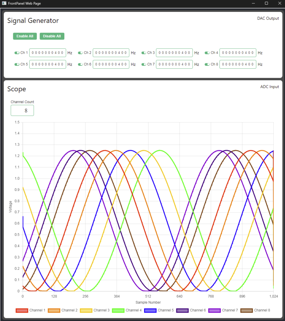
The MultiChannelDAQ example design features a GUI enabled by FrontPanel Platform, allowing users to manage 8 near-real-time DAC and ADC channels. The DAC channels function as a signal generator, producing sinusoidal waves using a CORDIC core, while the ADC channels function as an oscilloscope. The FrontPanel Platform software and gateware control two ADC and DAC controllers to operate the SZG-MULTIDAQ on the XEM8320. With FrontPanel Platform, users have access to open-source JavaScript libraries, and in this example, we utilize Chart.js to provide a versatile toolkit for data acquisition and oscilloscope display, serving as a foundation for more advanced projects.
Resources
Host Boards
SYZYGY Peripherals
Links
Getting Started
You’ll need:
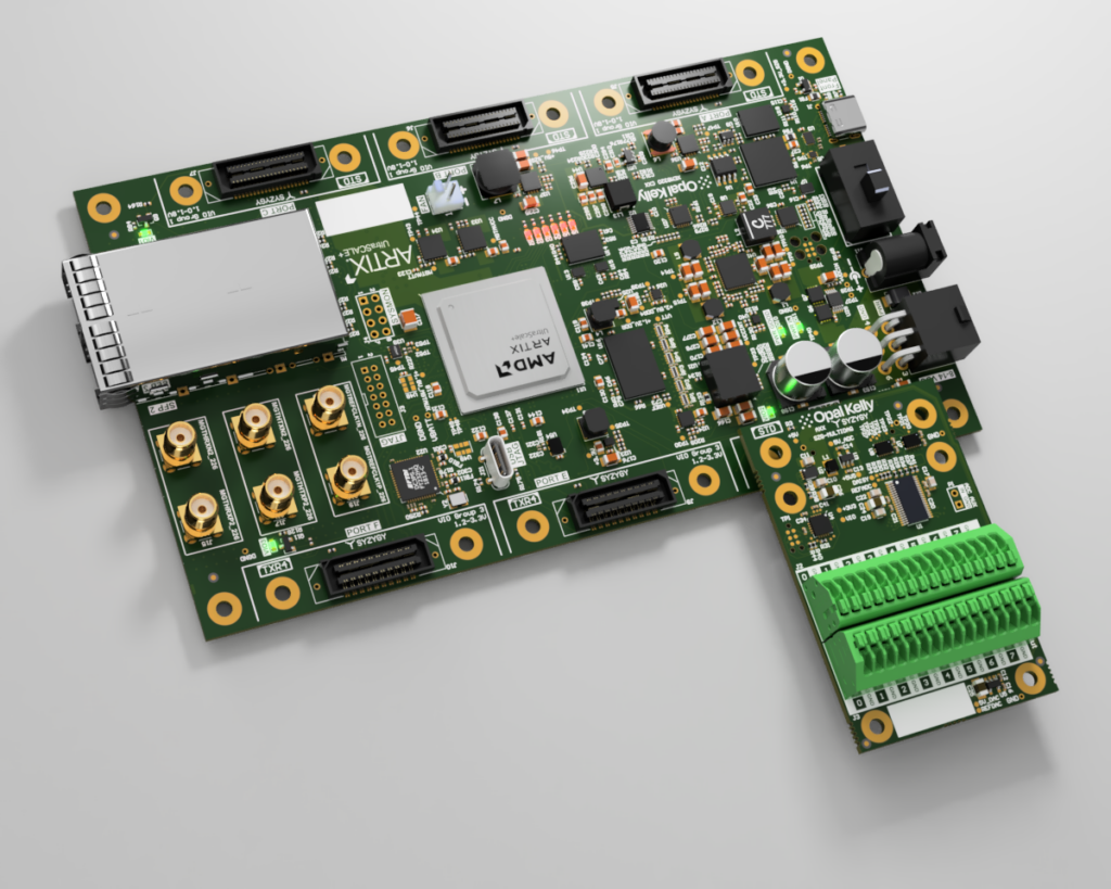
- XEM8320-AU25P with SZG-MULTIDAQ on Port D
- FrontPanel Platform 6.x installed (see the FrontPanel Platform Getting Started guide)
MultiChannelDAQ.fppfrom the latest MultiChannelDAQ Example Design release
To run the example design:
- Connect the SZG-MULTIDAQ to Port D on the XEM8320. Connect Channel 1 of the DAC to Channel 1 of the ADC using a piece of conductive wire. Connect the board to the PC via USB, and power on.
- Install the
MultiChannelDAQ.fppin the Application Launcher. - Drag the MultiChannelDAQ app card onto the device card.
How to Build the Software
Requirements
- Same development prerequisites as any FrontPanel Platform app (see the Building with NPM Create guide)
- The latest MultiChannelDAQ release source
Build steps
From the Software/ folder in the release:
npm install
npm run pack
The packaged .fpp is written to Software/output/MultiChannelDAQ.fpp. Pre-built bitfiles ship with the repository, so you do not need to rebuild the gateware first.
How to Build the Gateware
Requirements
- Latest MultiChannelDAQ-App-vX.Y release Source Code (zip or tar.gz)
- Vivado
Notice: Our tested version is v2023.2. Versions outside of this are not guaranteed to work. - FrontPanel Vivado IP Core v1.0.5 or higher
Building the Gateware
- Extract Example Design Release: Unzip/tar.gz the Example Design release and note the location for step 3.
- Add IP Cores to Vivado: Follow the instructions for Vivado IP Cores’ Distribution v1.0.5 or later and note the installation location for step 4.
- Navigate to Gateware Folder: Open the Vivado GUI and navigate to the MultiChannelDAQ gateware folder using the TCL Console.
- Example:
cd C:/path/to/MultiChannelDAQ/Gateware
- Example:
- Set IP Core Path: Set the fpdir variable to the IP core path.
- Example:
set fpdir C:/path/to/FrontPanel-Vivado-IP-Dist-vX.Y.Z
- Example:
- Run Setup Script: Run source project.tcl.
- Generate Bitstream: Click ‘Generate Bitstream’ once the project is ready.
Gateware Architecture Reference
ADC Path
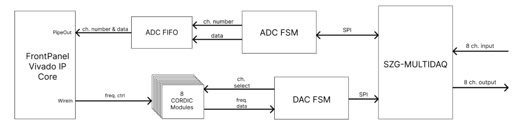
- ADC FSM (Finite State Machine): Manages SPI communication with the SZG-MULTIDAQ to receive digital values for 8 channels.
- ADC FIFO: Stores the digital values in a header-payload format. The header indicates the channel, and the payload contains the data.
- Data Flow: Digital values are gathered from SZG-MULTIDAQ via SPI → ADC FSM → ADC FIFO → FrontPanel Vivado IP Core (PipeOut) → Host Application.
DAC Path
- 8 CORDIC Modules: Generate sinusoidal output for each of the 8 DAC channels. Frequency is controlled by the user application.
- DAC FSM: Stripes through the 8 CORDIC outputs, collecting output data and transmitting it via SPI to the SZG-MULTIDAQ.
- Data Flow: Frequency control data from FrontPanel Vivado IP Core (WireIn) → 8 CORDIC Modules → DAC FSM → SZG-MULTIDAQ (via SPI).
Release Notes
Release downloads are available on GitHub at: opalkelly-opensource/MultiChannelDAQ Releases
MultiChannelDAQ Example Design 1.0
- Gateware built with Vivado 2023.2
- Initial Release