HLS Enhanced Design
Introduction

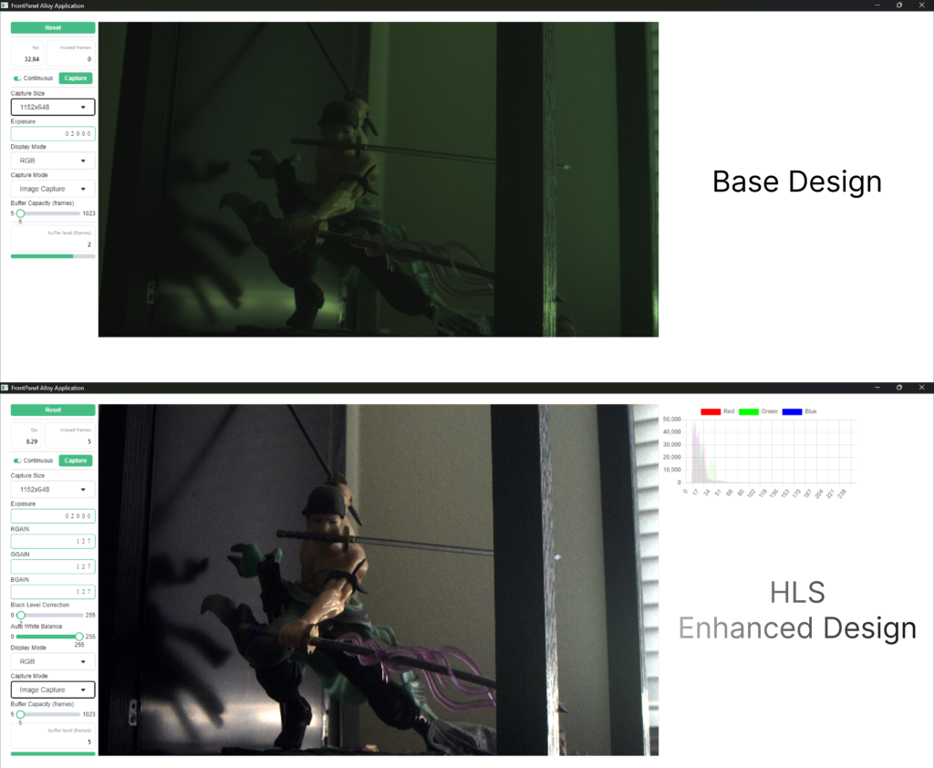
The base camera design is a straightforward system that captures images from the AR0330 sensor, buffers them, and transfers the images to a PC using a Frontpanel PipeOut component. By integrating Vitis Vision HLS, the design is enhanced to support advanced imaging applications, utilizing the extensive resources available in the Vitis Vision HLS Library to implement an Image Sensor Processing (ISP) pipeline.
The extended design showcases the seamless integration of Vitis Vision HLS with the existing Camera Reference Design. Additionally, a FrontPanel Platform GUI application is employed to control various aspects of the ISP, display the processed video feed, and present histogram statistics.

Credit
The HLS Enhanced Design was created in the summer of 2024 by our intern, Arnav. Thanks for all your hard work this summer, Arnav! We’re glad you could join us.
Resources
Learning Objectives
- Integrate Vitis Vision HLS with the existing Camera Reference Design.
- Use the FrontPanel Platform GUI application for control and display.
Release Notes
This project is included and released under the Camera Reference Design. Therefore release notes are located at: Camera Reference Design Release Notes.
Support
Our HLS Enhanced Design is provided AS-IS and is not guaranteed to be maintained. This also means that Opal Kelly does not officially support this asset, and it should be considered self-supported. As a result, we do not offer official technical support for issues that may arise from their use. Furthermore, we cannot assure its compatibility with all systems or guarantee its long-term functionality. Users utilizing these enhancements should be prepared to address challenges on their own or seek assistance through our community forums.
Project Design
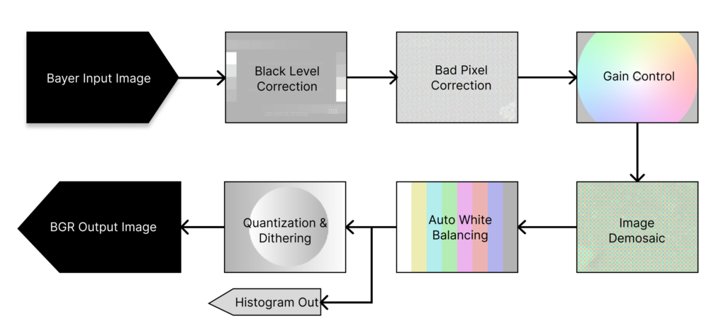
ISP Architecture

- Bayer Input Image: The raw image is captured from the sensor, in a GRGB Bayer pattern.
- Black Level Correction: The algorithm corrects the black and white levels of the overall image.
- Bad Pixel Correction: Identifies and corrects defective pixels (hot or dead pixels) to prevent artifacts in the final image.
- Gain Control: Adjusts the overall image brightness and colors.
- Image Demosaic: Interpolates color information from the Bayer pattern to create a full-color RGB image.
- Auto White Balancing: Adjusts the color balance to ensure neutral whites in the scene.
- Quantization & Dithering: Reduces the color depth of the image (e.g., from 12-bit to 8-bit) to match the display or storage requirements. Dithering is used to minimize quantization artifacts.
- BGR Output Image: The processed image is output in BGR format.
- Histogram Out: Optionally, a histogram of the final image can be generated to analyze the distribution of pixel values.
Gateware Architecture

The Gateware Architecture block diagram above illustrates the dataflow within the enhanced system. The base design is shown in black, while additions from the enhanced design are highlighted in green. Below, we describe two types of dataflow within this system: the image dataflow and the histogram dataflow.
Image Dataflow
- Path: SZG-Camera → Sensor Image Interface → ISP Pipeline →DDR4 → FrontPanel Image Interface→PipeOut
- Description: This path represents the primary flow for image processing. The image data is captured by the sensor, processed by the ISP Pipeline, and then sent to DDR4 for buffering. The buffered image is then pulled from the DDR4 and transmitted via Frontpanel PipeOut to the GUI.
Histogram Dataflow
- Path: ISP Pipeline (Histogram Generation)→ FIFO → FrontPanel Histogram Interface →PipeOut
- Description: This path is specifically for generating a histogram. The image data is sent to the ISP Pipeline, where a histogram is calculated. The histogram data is then stored in a FIFO (First-In-First-Out) buffer. This data is then transmitted via Frontpanel PipeOut to the GUI.
FrontPanel Platform GUI

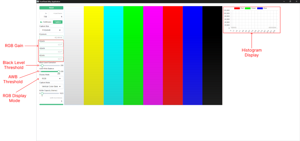
The Platform GUI Reference diagram above highlights the control and display elements we’ve added in the enhanced design, with arrows pointing to these new GUI components. Elements from the base design are not called out.
RGB Gain: Adjusts the overall image brightness and colors. This value sets the rgain, bgain, and ggain parameters as documented in the gaincontrol function of the Vitis Vision library.
Black Level Threshold: Sets the minimum signal level that is considered black. This value configures the black_level parameter as documented in the blackLevelCorrection function of the Vitis Vision library.
AWB Threshold: Adjusts the threshold for automatic white balance. This value sets the thresh parameter as documented in the AWB Functions of the Vitis Vision library.
Histogram Graph: Displays the histogram for RGB channels. Each color channel is overlaid on the same graph. You can choose which colors to display by enabling or disabling them using the color selectors in the top row.
RGB Display Mode: Displays the color image in RGB format. This mode serves as a translational step between the format received from the gateware and the format used by Platform to present the image. Specifically, the RGB mode translates from the AGBR format (where Alpha is first, followed by GBR color components) to the RGBA format used by the FrontPanel Platform GUI.
Getting Started
The goal of this getting started guide is to run the provided example design using prebuilt sources. This is a crucial first step to ensure correct hardware setup with known good sources.
- Requirements
Camera-ExampleDesign-HLS-vX.Y.asarfrom the latest Camera-ExampleDesign-vX.Y GitHub release.- FrontPanel 6.0.0 beta or higher
- XEM8320-AU25P
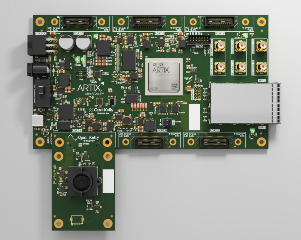
- SZG-Camera on Port A of the XEM8320-AU25P
Running the Prebuilt Platform Application
- Open the FrontPanel Platform application.
- Install the Camera-HLS app by clicking the ‘+’ button in the Installed Applications panel. Then locate the
Camera-ExampleDesign-HLS-vX.Y.asarfile you downloaded from the latest Camera-ExampleDesign-vX.Y release. For more details, see Building the Template App Guide. - Install the SZG-Camera onto Port A of the XEM8320-AU25P.
- Connect the XEM8320 device to your PC.
- Power on the XEM8320.
- Click and drag the Camera-HLS Application card to the available XEM8320 device.
Building the Platform Application
Requirements
- Latest Camera-ExampleDesign-vX.Y release Source Code (zip or tar.gz)
szg-camera-xem8320-hls.bitfrom the Camera-ExampleDesign-vX.Y-Bitfiles.zip bundle located in the latest Camera-ExampleDesign-vX.Y release- Install prerequisites from the Development Guide
- FrontPanel 6.0.0 installed
Steps
- Open Folder: Open the
ExampleProjects/Camera/Software/FP-Platform-HLSfolder in Visual Studio Code. This folder is located in the Camera-ExampleDesign-vX.Y release Source Code. - Add Prebuilt Bitfile: Copy the
szg-camera-xem8320-hls.bitto theassetsfolder. - Install Dependencies: Run
npm installwithin a Visual Studio command terminal. - Build Project: Run
npm run packwithin a Visual Studio command terminal. - Locate Output: The
app.asarfile is located in theoutputfolder. - Start FrontPanel Platform: Open FrontPanel Platform Application.
- Install Application: Install the app.asar by clicking the ‘+’ button in the Installed Applications panel of the FrontPanel Platform. For more details, see Building the Template App Guide.
- Run Application: Click and drag the Camera-HLS Application card to an available XEM8320 device.
Building the Gateware (Windows 10)
- Clone the Camera repository.
- Initialize all submodules:
git submodule update --init --recursive - Follow this guide to install and setup OpenCV on Windows 10: Install/Setup OpenCV on Windows 10
- After installing OpenCV, follow the guide Create and Run a Vitis Vision Library Example on Windows 10 to create and run a Vitis Vision Library example. However, use the HLS files provided in the
design-resources/ExampleProjects/Camera/HDL/XEM8320/SZG-Camera-HLS/HLS/ISPfolder instead of the example files shown in the guide. - For the following steps in the “Create and Run a Vitis Vision Library Example on Windows 10” guide, replace the specified lines with the instructions below. We use relative paths as we have a local copy of the Vitis Vision Library as a Git Submodule.
- 3.b (no substitution required)
-I ../config -I ../../Vitis_Libraries/vision/L1/include -I ./ -D__SDSVHLS__ -std=c++14 - c.i (substitute your OpenCV installation path)
-I ../config -I C:/<your OpenCV location>/build/install/include -I ../../Vitis_Libraries/vision/L1/include -I ./ -D__SDSVHLS__ -std=c++14 - c.ii (no substitution required)
../../../../../../Vitis_Libraries/vision/data/128x128.png - c.iii (substitute your OpenCV installation path)
-L C:/<your OpenCV location>/build/install/x64/mingw/lib -lopencv_imgcodecs440 -lopencv_imgproc440 -lopencv_calib3d440 -lopencv_core440 -lopencv_highgui440 -lopencv_flann440 -lopencv_features2d440 - d.i (no substitution required)
../../../../../../Vitis_Libraries/vision/data/128x128.png
- 3.b (no substitution required)
- Enable the following option in
hls_config.cfg:When true enables optimized compilation for both csim and cosim and disables csim Code Analyzer. When false uses debug mode compilation. - Run “C Synthesis” and “Package” in the current Vitis HLS project.
When building on Windows, if you encounter an error stating that the path length exceeds 260 characters, move theHDLfolder closer to the root directory before starting “C Synthesis” and “Package”. For more details, refer to the general notice in readme.md. - Run the
project.tclscript located in thedesign-resources/ExampleProjects/Camera/HDL/XEM8320/SZG-Camera-HLS/folder in Vivado to create the Vivado project. - Import the XEM8320 FrontPanel HDL from the FrontPanel SDK Installation.
- Run “Generate Bitstream” in Vivado.
FrontPanel Platform Performance
The HLS Enhanced design was also an exhibition project to explore the capabilities of FrontPanel Platform, pushing the system further than the base Platform application. The Platform communication channel does have reduced performance compared to using our C++ API device communication channel directly. The additional stress placed on the Platform communication channel in the HLS Enhanced design led to the frame buffer filling up faster than Platform could process image and histogram data. This resulted in image backup in the DDR4 memory and the eventual dropping of frames to prevent overflow. Below, we highlight some of the performance behaviors observed during the HLS Enhanced Platform application.
Background
The Platform backend communication can only handle a limited number of calls per second to the device. The execution time for different operations varies:
- Wires and Triggers: Provide a consistent time segment required to execute.
- Pipes: Execution time varies based on the requested data size.
These time segments contribute to the total communication channel time. If the Platform communication channel cannot meet the system’s bandwidth and command execution requirements, commands will backlog. This backlog occurs in the WorkQueue, where commands are queued and processed sequentially.
Below summarizes the current Image Acquisition and Histogram Acquisition:
- Two asynchronous processes (image acquisition and histogram acquisition) are placing work tickets into the WorkQueue at set intervals.
- Each ticket involves a handshaking process with the gateware, including polling with a WireOut for data availability and acquiring data with a PipeOut.
- The device processes these tasks one at a time in the order the tickets are placed into the WorkQueue.
Original Platform Camera Application Observations
Here are our observations from testing on a work PC, comparing the original Platform camera application with the HLS Enhanced design. The primary focus is whether the image buffer experiences backups. We provide tables with various tests and key details, including:
- Resolutions: Three supported by the SYZYGY Camera.
- Image Transfer Size: Size in bytes during PipeOut API calls.
- Delay Interval: Time between successive acquisitions.
- Buffer Backup: Indication of whether image buffer backups occurred.
| Resolution | Image Size (Bytes) | Delay Interval | Image Buffer Backup |
|---|---|---|---|
| 768×432 | 331,776 | 5ms | No |
| 1152×648 | 746,496 | 5ms | No |
| 2304×1296 | 2,985,984 | 5ms | Yes |
HLS Enhanced Platform Application Observations
The demosaic output increases the image size to 3 bytes per pixel, with 1 byte each for red, blue, and green color components. Additionally, we send an alpha value of 1 byte per RGB pixel, making a total of 4 bytes per pixel transmitted over FrontPanel. This contrasts with the ‘Original Platform Camera Application,’ where only a Bayer pattern is sent over FrontPanel, which is just 1 byte per pixel.
With Histogram Acquisition
The image acquisition and histogram acquisition processes both place commands into the WorkQueue at set intervals. Each process adds work tickets for its respective task, which are handled sequentially by the device through the WorkQueue.
| Size (Bytes) | Delay Interval |
|---|---|
| 768 | 240ms |
| Resolution | Image Size (Bytes) | Delay Interval | Image Buffer Backup |
|---|---|---|---|
| 768×432 | 1,327,104 | 2ms | Yes |
| 1152×648 | 2,985,984 | 2ms | Yes |
| 2304×1296 | 11,943,936 | 2ms | Yes |
Without Histogram Acquisition
In this test, we disabled the asynchronous process that adds tasks to the WorkQueue for histogram acquisition. The goal is to determine if reducing the load on the device helps resolve image buffer backup issues.
| Resolution | Image Size (Bytes) | Delay Interval | Image Buffer Backup |
|---|---|---|---|
| 768×432 | 1,327,104 | 2ms | Yes |
| 1152×648 | 2,985,984 | 2ms | Yes |
| 2304×1296 | 11,943,936 | 2ms | Yes |
Without Histogram Acquisition and Without Delay Interval
In addition to disabling the asynchronous histogram acquisition process, we also removed the delay associated with adding new tasks to the WorkQueue for image acquisition. The goal is to determine if saturating the queue with additional image acquisition tasks helps reduce image buffer backups.
| Resolution | Image Size (Bytes) | Delay Interval | Image Buffer Backup |
|---|---|---|---|
| 768×432 | 1,327,104 | 0ms | No |
| 1152×648 | 2,985,984 | 0ms | Yes |
| 2304×1296 | 11,943,936 | 0ms | Yes |
Proposal
To address the bandwidth and command execution rate issues, we propose the following:
- Convert to C++ Using Our FrontPanel C++ API: Transition the design to use our FrontPanel C++ API for improved performance, bypassing the limitations of the Platform communication channel and leveraging the full bandwidth and command execution capabilities of the API.
- Bandwidth Reduction of Image Acquisition:
The execution time of the PipeOut varies with the data size. By reducing the data size, we can decrease execution time and reduce the demand on the Platform communication channel, thus better meeting the bandwidth and command execution rate requirements of the HLS-enhanced design.- Remove Alpha Value Transmission:
Currently, the gateware transmits the Alpha value (set to 0xFF for full opacity) along with RGB values, totaling 4 bytes per pixel, from the gateware to the Platform application over the Platform communication channel. To reduce bandwidth usage, we can hardcode the Alpha value to 0xFF on the Platform application side, and send only RGB values from the gateware. This reduces the per-pixel data from 4 bytes to 3 bytes. - Change Data Format:
Another method to reduce the data size is to change the format from RGB888 to a more compact format, such as RGB565 or YUV. This would reduce the amount of data transferred over the Platform communication channel, reducing bandwidth utilization.
- Remove Alpha Value Transmission:
- Enhance and Optimize WorkQueue Implementation: Enhance our provided WorkQueue implementation to allow setting priorities for tasks posted to the WorkQueue. For example, assigning a higher priority to image acquisition tasks over histogram acquisition tasks could improve overall system responsiveness. Additionally, implement a profiler feature for the Platform WorkQueue to gain insights into available bandwidth and idle time. This profiler will help you determine how much idle time the device has, enabling you to adjust the rate of commands and optimize delay intervals. This approach ensures that you are fully utilizing the bandwidth of the channel. Our WorkQueue source code is freely available, allowing you to modify it as needed to suit your application.
Conclusion
Implementing any of these strategies—or a combination of them—such as optimizing command management, reducing data size, prioritizing tasks, or transitioning to our C++ API, would help enhance overall system efficiency. If you transition to the C++ API, you can bypass the limitations of the Platform communication channel entirely, leveraging the full capabilities of direct device communication.
Future Directions
Implement Pixel Binning for Better Low-Light Performance
Binning should be as easy as adding:
await this._DeviceI2C.Write16(AR0330Device.AR0330_REG_READ_MODE, 0x1200);Code language: CSS (css)Likely added to SetupOptimizedRegisterSet()
We need to evaluate adding this feature and the best location for it.
Add AXI-Lite Control to Video Pipeline
We need to integrate AXI Lite control into our video pipeline. This will involve utilizing our FrontPanel to AXI-Lite Bridge to manage the pipeline.
Reason:
Integrating AXI Lite control is important because it is the standard method for communicating control in AMD’s ecosystem. All Vitis Vision examples generate control to an AXI-Lite interface by default. Including this in our example is not for speed or efficiency reasons but to demonstrate to our customers how to incorporate AXI-Lite control into their designs.
Tasks:
- Port API:
- Port either the C++ or Python API to JavaScript/TypeScript. This will allow us to interact with the AXI Lite registers in Platform.
- Implement AXI Lite Control:
- Use the ported API to send AXI Lite register updates to the video pipeline.
- Implement various pipeline controls such as color gain adjustments.
Update FrontPanel version capabilities according to implementation needs
Currently, we have copied the FrontPanel Platform application from the Platformfolder and made modifications to the copy in the Platform-HLS folder. This approach results in a lot of reused code. Ideally, we could use the Capability parameter in the gateware to inform the Platform application about the new capabilities of the ISP pipeline and present the appropriate options to the user. This would allow us to maintain a single Platform application instead of two.
Implementation Steps:
- Increment the Capability parameter in the gateware.
- Ensure the Platform application reads the Capability parameter from the gateware.
- Use the Capability parameter to dynamically present the appropriate controls for new capabilities in the Platform application.
- Update the application to correctly display only the RGB format option.
- Temporarily limit the use of the largest resolution due to current issues.
This approach will streamline our application and reduce redundancy.
Create a Build Script
Create a build script to automate the process of building HLS, then creating a Vivado project, and importing the necessary files and HLS. The script should streamline the workflow similar to the one found in the DAC-ADC example project: FFTScope Example Project.
Known Issues
Image and Histogram Data Synchronization Issue with Increased DDR4 Buffer Size
The current system architecture routes image data through DDR4 memory and histogram data through a FIFO, utilizing separate data flow paths. This separation results in synchronization issues. When the DDR4 memory buffer size is increased from 5 to a larger value like 512, a noticeable delay arises between what the image sensor captures and what is presented in the application due to image buffer backup, which is further explained in the “Platform Performance” section above. The histogram data no longer aligns with the corresponding image frame. Instead, it reflects data from the most recent image processed by the ISP pipeline, not the frame currently displayed in the Platform application.
Resolution
To resolve these issues, we need to store the histogram data with its associated image frame in the DDR4 memory. The steps to implement this are outlined below.
Implementation Steps
- Bring in Histogram Size via WireIn
- Add the histogram size as a WireIn, similar to how
img_sizeis brought in on a WireIn. - Reference: okcamera.v: Line 252
- Add the histogram size as a WireIn, similar to how
- Update Address Calculation in
imgbuf_coordinator.v- Dish out addresses that account for the histogram size.
- Reference: imgbuf_coordinator.v: Line 146
input_buffer_addr_next <= input_buffer_addr + (img_size >> 1) + hist_size;
- Coordinate Writing in
image_if.v- First, write the AXI Video stream frame into the FIFO, followed by writing the AXI Stream histogram data into the FIFO. Then reset and wait for the next frame.
- Reference: image_if.v: Line 207
- Update
readout_countofhost_if.v- Modify the
readout_countto account for the additional histogram data size.Reference: okcamera.v: Line 445
.readout_count (img_size_memclk + hist_size_memclk), // input [31:0] - Modify the
- Update Software to Request Combined Data
- Modify the software to request
img_size + hist_sizedata. - Reference: FrontPanelCamera.ts: Line 384
const totalSize = img_size + hist_size; const data = await this.fp.readFromPipeOut(0xa0, totalSize); // Parse out the image from the histogram data and send them to the appropriate display components.
- Modify the software to request
By implementing these steps, we can ensure that the histogram data is synchronized with its associated image frame and stored in DDR4 memory.
Largest resolution has issues with screen tearing
Investigate and resolve the screen tearing issues occurring at the largest resolution.
Testbench Error: Assertion Failed in ap_int_base.h
An assertion error occurs in the testbench:
Assertion failed: (index >= 0) && ("Attempting to read bit with negative index"), file C:/<Path to Vitis_HLS installation>/Vitis_HLS/2024.1/include/etc/ap_int_base.h, line 1139
Code language: JavaScript (javascript)
Temporary Resolution
Enable the following option in hls_config.cfg:
When true enables optimized compilation for both csim and cosim and disables csim Code Analyzer. When false uses debug mode compilation.
Code language: JavaScript (javascript)
Next Steps
Further investigation is required to identify the root cause.