Gigabit Transceivers
The ECM1900 provides access to 24 high-speed serial transceiver pairs and associated reference clocks. See the pins list to reference the mezzanine connector pin connections.
- 20 GTH pairs (Rx + Tx) corresponding to PL quads 223, 224, 225, 226, and 227 are available on mezzanine connector MC2.
- MGTREFCLK0 inputs on PL quads 223, 224, 225, 226, and 227 are connected to the on-board Silicon Labs Si5341B clock generator. See Clock Generator.
- MGTREFCLK1 inputs on PL quads 223, 224, 225, 226, and 227 are available on mezzanine connector MC2.
- 4 GTR pairs (Rx + Tx) corresponding to PS quad 505 are available on mezzanine connector MC2.
- MGTREFCLK0 input on PS quad 505 is connected to the on-board Silicon Labs Si5341B clock generator. See Clock Generator.
- MGTREFCLK1 and MGTREFCLK2 inputs on PS quad 505 are available on mezzanine connector MC2.
- MGTREFCLK3 input on PS quad 505 is connected to an optional on-board clock oscillator, reference designator U22. The PCB footprint is designed for Abracon part number ASDMPL or equivalent. Reference designator C239 is intended for a decoupling capacitor, connected to U22 pin 6. (0402 footprint). The LVDS output of U22 is connected to MGTREFCLK3 using 0.01μF AC coupling capacitors C238 and C240.
AC-Coupling
0.01μF AC-coupling capacitors are installed between the expansion connectors and the FPGA for all MGTREFCLK signals.
AC-coupling capacitors are not installed for any of the GTH transmit or receive pairs. If AC coupling is desired or required for the serial application, they should be installed on the peripheral side (your board).
IBERT Configuration
Xilinx provides the IBERT tool to test and experiment with gigabit transceivers. The settings below are compatible with the XEM8350 using Vivado 2019.1:
| PROTOCOL DEFINITION | ||
|---|---|---|
| Protocol | Custom 1 | |
| Line Rate | 12.5 Gbps | |
| Data Width | 40 | |
| Ref Clk | 100.000 MHz | |
| Quad Count | 7 | |
| PLL | QPLL0 | |
| PROTOCOL SELECTION | ||
| GTX Location | Protocol Selected | Refclk Selection |
| QUAD_126 | Custom 1 / 12.5Gbps | MGTREFCLK0_127 |
| QUAD_127 | Custom 1 / 12.5Gbps | MGTREFCLK0_127 |
| QUAD_128 | Custom 1 / 12.5Gbps | MGTREFCLK0_127 |
| QUAD_224 | Custom 1 / 12.5Gbps | MGTREFCLK0_225 |
| QUAD_225 | Custom 1 / 12.5Gbps | MGTREFCLK0_225 |
| QUAD_226 | Custom 1 / 12.5Gbps | MGTREFCLK0_225 |
| QUAD_227 | Custom 1 / 12.5Gbps | MGTREFCLK0_225 |
| QUAD_228 | None | None |
| CLOCK SETTINGS | ||
| Add RXOUTCLK Probes | Unchecked | |
| Clock Type | System Clock | |
| Source | External | |
| I/O Standard | LVDS | |
| P Package Pin | AM22 | |
| Frequency | 200 MHz | |
| Enable DIFF Term. | Unchecked |
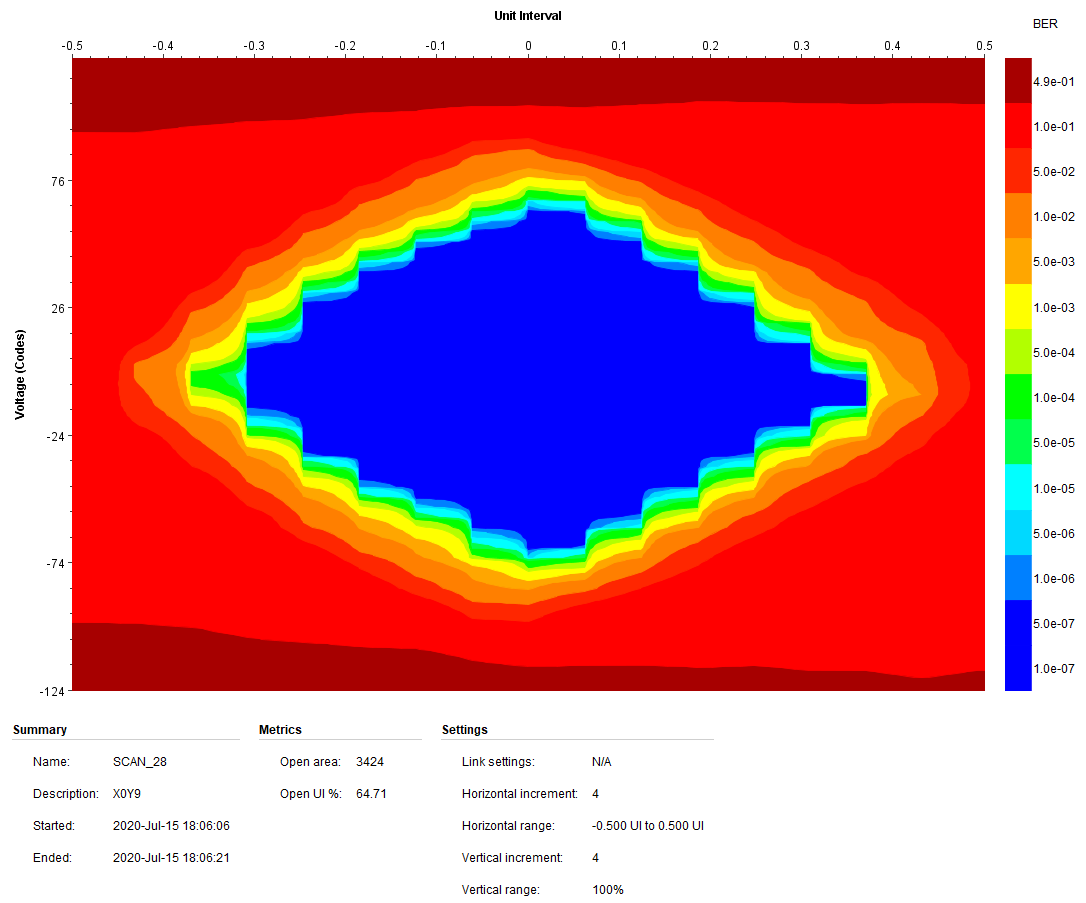
Gigabit Transceiver IBERT Performance
Xilinx’s IBERT tool enables an automated self-measurement of a GTH channel’s eye diagram when used in a loopback mode. Eye diagrams for two different speeds were captured using this tool with a simple loopback peripheral attached to the expansion headers. While results may vary, these are typical captures and actually represent the worst case capture over all channels for the respective rates.
Note that in loopback modes, it can be helpful to disable the GBT DFE (decision feedback equalizer) to avoid over-compensation. The TX Diff Swing must also be set so that it does not over saturate the receiver.
8 Gbps / XEM8350-KU060
Measurement taken with DFE disabled, TX Diff Swing set to 600mV.
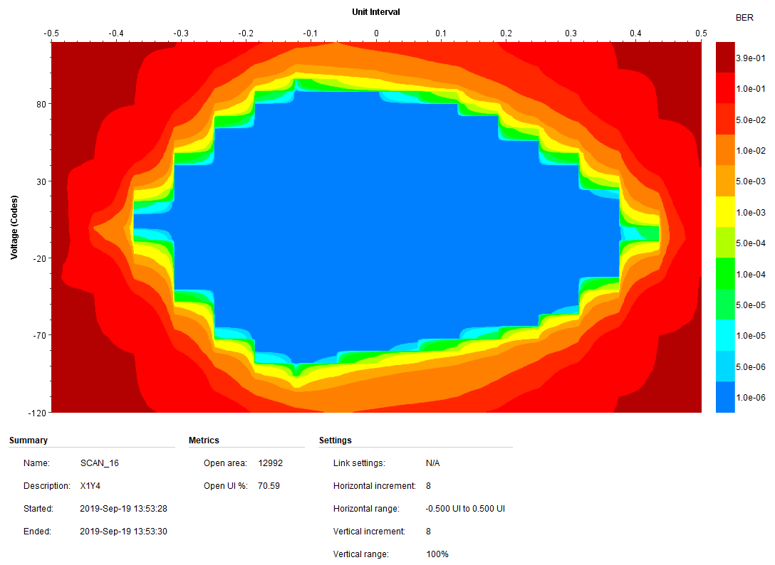
12.5 Gbps / XEM8350-KU060
Measurement taken with DFE enabled, TX Diff Swing set to 320mV and RXTERM set to 260mV.