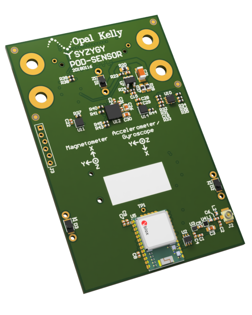
SZG-SENSOR

A SYZYGY standard all-in-one multi-sensor module with the following capabilities:
- Ambient Light & Proximity Sensor
(Silicon Labs Si1153-AA00-GMR) - Three IR illuminator LEDs
- GNSS Module, GPS / Galileo / GLONASS / BeiDOu
(u-blox CAM-M8Q) - Internal or external GPS antenna
- Accelerometer, gyroscope, magnetometer
(ST Microelectronics LSM9DS1) - Pressure sensor
(ST Microelectronics LPS22HB) - Temperature and humidity sensor
(ST Microelectronics HTS221)
Resources
- Aligni PLM – See the Attachments tab for schematics.
- SYZYGY Specification
- SYZYGY GitHub Site – Several projects that could be helpful.
- Product Page
SYZYGY Information
Compatibility Table
| COMPATIBILITY PARAMETER | SPECIFICATION |
|---|---|
| Port type | SYZYGY Standard |
| Width | Single |
| 5V supply required | Yes |
| Nominal 5V supply current | 150mA |
| Nominal 3.3V supply current | < 10mA |
| VIO supply voltage | 1.8V to 3.3V |
| Nominal VIO supply current | < 10mA |
| Total number of I/O | 28 |
| Number of differential I/O pairs | 0 |
DNA Data
This data is stored in the SYZYGY DNA microcontroller on the SZG-SENSOR peripheral.
| DNA PARAMETER | DATA |
|---|---|
| Max 5V Load | 150 mA |
| Max 3.3V Load | 0 mA |
| Max VIO Load | 10 mA |
| IS_LVDS | False |
| IS_DOUBLEWIDE | False |
| VIO Min | 1.8V |
| VIO Max | 3.3V |
Pinout
The source of the following pinout information is the SZG-SENSOR schematic. This pinout follows the SYZYGY specification for STD ports.
- Column
PIN NUM (J1)lists the pin number on the SYZYGY specification’s Standard Samtec connector, this is reference designator J1 in the schematic. - Column
SIGNAL NAMElists the SYZYGY specification’s name for this pin’s connection. - Column
SCHEMATIC NETlists the net name found in the SZG-SENSOR’s schematic for the connection.
| PIN NUM (J1) | SIGNAL NAME | SCHEMATIC NET |
|---|---|---|
| 5 | S0 | CAM_M8Q_SPI_CS_N |
| 6 | S1 | HTS221_CS |
| 7 | S2 | CAM_M8Q_EXTINT |
| 8 | S3 | HTS221_DRDY |
| 9 | S4 | CAM_M8Q_TIMEPULSE |
| 10 | S5 | HTS221_SPI_SDI_SDO |
| 11 | S6 | CAM_M8Q_D_SEL |
| 12 | S7 | LSM9DS1_DEN_AG |
| 13 | S8 | CAM_M8Q_SAFEBOOT_N |
| 14 | S9 | LSM9DS1_INT2_AG |
| 15 | S10 | CAM_M8Q_UART_TXD_SPI_MISO |
| 16 | S11 | LSM9DS1_INT1_AG |
| 17 | S12 | CAM_M8Q_UART_RXD_SPI_MOSI |
| 18 | S13 | LSM9DS1_INT_M |
| 19 | S14 | GNSS_EXT_ANT_EN |
| 20 | S15 | LSM9DS1_CS_M |
| 21 | S16 | LPS22HB_SPI_SDI_SDO |
| 22 | S17 | LSM9DS1_DRDY_M |
| 23 | S18 | LPS22HB_SPI_SDO |
| 24 | S19 | LSM9DS1_CS_AG |
| 25 | S20 | LPS22HB_INT_DRDY |
| 26 | S21 | LSM9DS1_SPI_SDO_M |
| 27 | S22 | LPS22HB_CS |
| 28 | S23 | LSM9DS1_SPI_SDO_AG |
| 29 | S24 | SI1153_SCL |
| 30 | S25 | LSM9DS1_SPI_SDI_SDO |
| 31 | S26 | SI1153_SDA |
| 32 | S27 | SI1153_INT |
| 34 | C2P_CLKp | SPI_CLK |
| SENSOR | INTERFACE TO FPGA | TYPE |
|---|---|---|
| Si1153 | I2C | Ambient Light + Proximity |
| CAM-M8Q | UART | GNSS (GPS, Galileo, GLONASS, BeiDou) |
| HTS221 | SPI* | Humidity + Temperature |
| LPS22HB | SPI* | Pressure |
| LSM9DS1 | SPI* | Accelerometer + Gyro + Magnetometer |
*All sensors connected over the SPI interface share the same SPI clock signal connected to pin 34 (C2P_CLKp) of the SYZYGY connector.
Design
The circuits used in this design are heavily influenced by the respective manufacturer datasheets and evaluation board application circuits. Please refer to the references below for more information