BRK7360 Breakout Board
IPMI EEPROM
The XEM7360 may optionally read peripheral information and configuration data from a small EEPROM on the peripheral. If available, the EEPROM can be used to automatically set the voltages for the three programmable voltage regulators on the XEM7360. An EEPROM is installed on the BRK7360 but is not loaded with any configuration. Use Opal Kelly’s IPMI EEPROM Generator Tool to generate an EEPROM image, then use FrontPanel’s Flash Programming Tool to download the image to the EEPROM.
Peripherals and Connectors
The table below summarizes the various connectors on the BRK7360. The XEM7360 Pin List has connection information in the “BRK7360” column. Additionally, please refer to the schematics and layout available online for detailed connection diagrams.
| CONNECTOR TYPE | REFDES | FPGA MGT QUAD | |
|---|---|---|---|
| U.FL | J12 – J15 | GTX115 | TxRx 0 |
| U.FL | J8 – J11 | GTX115 | TxRx 1 |
| SFP | J3 | GTX115 | TxRx 2 |
| SFP | J2 | GTX115 | TxRx 3 |
| SMA | J4 – J7 | GTX116 | TxRx 0 |
| SATA | J18 | GTX116 | TxRx 1 |
| SATA | J17 | GTX116 | TxRx 2 |
| SATA | J16 | GTX116 | TxRx 3 |
Clock Oscillator
The onboard oscillator is provided as an alternate external reference for transceivers.
| BRK PCB REVISION | Freq | FPGA MGT QUAD | REFCLK |
|---|---|---|---|
| 20151022 | 100Mhz | GTX115 | 0 |
| BXX | 156.25Mhz | GTX115 | 0 |
SFP Transceiver Sockets
The BRK7360 has two SFP cages installed. Their MGT connections are listed above.
The control signals for the SFP ports are connected as shown in the table below.
| RefDes | Pin | Signal | FPGA Pin |
|---|---|---|---|
| J2 | 2 | Tfault | M16 |
| J2 | 3 | Tdis | L17 |
| J2 | 4 | MOD_DEF2 | K18 |
| J2 | 5 | MOD_DEF1 | L18 |
| J2 | 6 | MOD_DEF0 | K20 |
| J2 | 7 | Rate Select | M17 |
| J2 | 8 | LOS | D15 |
| J3 | 2 | Tfault | C14 |
| J3 | 3 | Tdis | H12 |
| J3 | 4 | MOD_DEF2 | J14 |
| J3 | 5 | MOD_DEF1 | A12 |
| J3 | 6 | MOD_DEF0 | A15 |
| J3 | 7 | Rate Select | A13 |
| J3 | 8 | LOS | B15 |
Optical transceivers modules are not included with the BRK7360. The following Finisar part is one example SFP module:
| MANUFACTURER | PART NUMBER | DIGI-KEY P/N | APPROXIMATE COST |
|---|---|---|---|
| Finisar | FTLF8524P2BNV | 775-1045-ND | $53.55 / each |
Schematic and Design Files
The BRK7360 schematics and design files are available in the Downloads section of the Pins website.
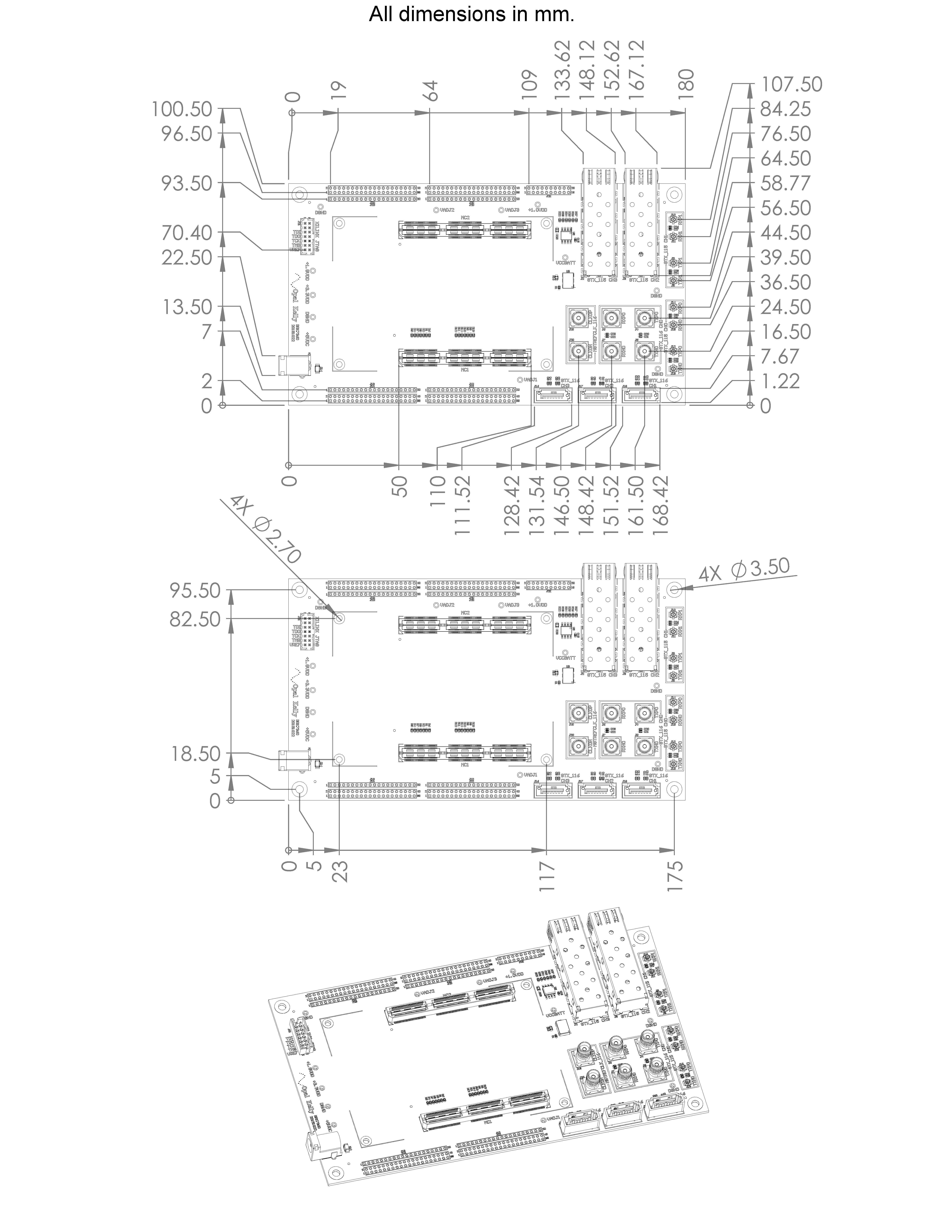
Mechanical Drawing