XEM8370
LEDs
Power LEDs
The XEM8370 includes two LED indicators for power status.
| LED | ON CONDITION |
|---|---|
| PWR IN (D11) | +VDCIN present, no over-voltage or reverse voltage faults |
| PWR GOOD (D12) | All on-board power supplies active and within expected range (Does not include VIOx supplies) |
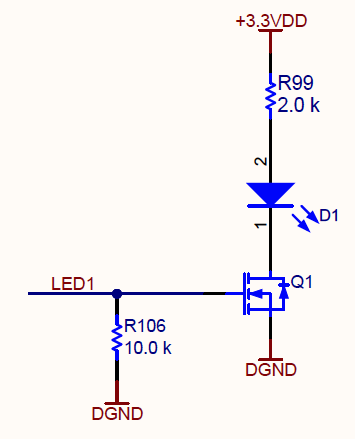
User LEDs
There are eight LEDs, each of which is controlled by FPGA pins as shown in the table below.
| LED | FPGA PIN |
|---|---|
| D1 | E20 |
| D2 | F20 |
| D3 | G20 |
| D4 | E21 |
| D5 | F23 |
| D6 | G24 |
| D7 | F24 |
| D8 | F25 |
The LED anodes are connected through a current limiting resistor to +3.3 V and the cathodes wired through NMOS transistors to the FPGA I/O on Bank 70. To turn ON an LED, the FPGA pin should be at logic 1. To turn OFF an LED, the FPGA pin should be at logic 0.