SYZYGY Ports
Port Summary
The BRK8370 provides 5 SYZYGY ports. A summary of details of each port is listed in the table below.
The XEM8370 firmware is configured to connect up to 16 SYZYGY ports, the maximum allowed in the SYZYGY standard. These ports are designated SYZYGY 0 to SYZYGY 15. The BRK8370 provides physical access to 5 of those possible SYZYGY ports. The BRK8370’s SYZYGY ports are designated PORT A to PORT E. See the table below for the mapping between these virtual and physical SYZYGY ports on the BRK8370. The SYZYGY port number for a physical port is determined by the Geographical Address resistor connected to the port, as defined in the SYZYGY DNA Specification.
| BRK8370 PORT | XEM8370 PORT | VIO GROUP | TYPE | BRK8370 REFDES | BANK |
|---|---|---|---|---|---|
| PORT A | SYZYGY 4 | 2 | STD | J3 | I/O 67 and 69 |
| PORT B | SYZYGY 5 | 2 | STD | J4 | I/O 67 |
| PORT C | SYZYGY 10 | 3 | STD | J6 | I/O 64 |
| PORT D | SYZYGY 11 | 3 | STD | J7 | I/O 66 |
| PORT E | SYZYGY 12 | 3 | TXR4 | J14 | GTH 224 (REFCLK 0) I/O 66 |
Configuration of the XEM8370 connected TXR4 ports requires the XEM8370_SZG_TXR4_PORTS device setting to specify which ports are TXR4 type. This requires placing a 1 in bit positions that correspond to the connected TXR4 ports.
The BRK8370 has one TXR4 port (Port E) which uses the address resistor associated with location SYZYGY 12. To configure Port E as a TXR4 port, bit 12 to needs to be set to 1. That makes the correct XEM8370_SZG_TXR4_PORTS value 0x1000 to configure Port E as TXR4 on the BRK8370.
See Device Settings for more information.
Impedance and Length Matching
Single-ended fabric I/O is routed to the SYZYGY ports with 50Ω characteristic impedance. Differential fabric I/O is routed to the SYZYGY ports as 100Ω differential impedance. Fabric I/O routing as been matched on the BRK8370 to each SYZYGY port as much as possible. Differential pair routing has been matched to at least 5 mils within pairs. This matching, and the length values in the SYZYGY Compatibility Table below, represent the traces from mezzanine connectors to the SYZYGY ports.
SYZYGY Compatibility Table
|
PARAMETER |
PORT A |
PORT B |
PORT C |
PORT D |
PORT E |
|---|---|---|---|---|---|
|
Total 5V Supply Current |
4.5 A |
||||
|
Total 3.3V Supply Current |
7 A (Shared with QSFP) |
||||
|
Port Groups |
Group 2: A, B |
Group 3: C, D, E |
|||
|
Port Type |
Standard |
Standard |
Standard |
Standard |
Transceiver (TXR4) |
|
Bank Type |
HP |
HP |
HP |
HP |
GTH + HP |
|
VIO Supply Voltage Range |
0.95 – 1.8 V |
0.95 – 1.8 V |
|||
|
Total VIO Supply Current |
2 A |
2 A |
|||
|
Port Spacing |
Double-Wide Spacing |
Double-Wide Spacing |
Single-Wide |
||
|
I/O per Port |
28 total (8 DP) |
28 total (8 DP) |
28 total (8 DP) |
28 total (8 DP) |
10 total |
|
Length Matching |
3557 – 3561 mills |
2720 mills |
3558 – 3562 mills |
4242 mills |
I/O: 4298 mills Transceivers: 2760 – 3823 mills |
Peripheral Mounting
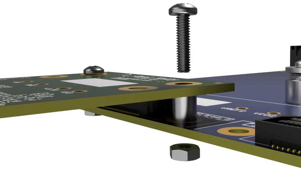
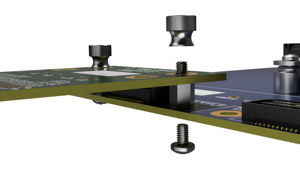
SYZYGY peripherals can be mechanically connected together using the carrier and peripheral mounting holes. Below are some suggested mounting hardware options. The Standard Hardware mounting kit is available from the accessories section of our store.
| PART | SUPPLIER | PART NUMBER | QUANTITY PER PORT |
|---|---|---|---|
| 5mm Unthreaded Standoff | McMaster-Carr | 94669A098 | 2 |
| Pan Head Phillips 10mm Bolt | McMaster-Carr | 92000A106 | 2 |
| Hex Nut | McMaster-Carr | 91828A113 | 2 |

| PART | SUPPLIER | PART NUMBER | QUANTITY PER PORT |
|---|---|---|---|
| Male-to-Female 5mm Standoff | McMaster-Carr | 93655A001 | 2 |
| Pan Head Phillips 4mm Bolt | McMaster-Carr | 92000A102 | 2 |
| Thumb Nut | McMaster-Carr | 96445A320 | 2 |
