USB 3.0 Host Interface
There are 41 signals that connect the on-board USB microcontroller to the FPGA. These signals comprise the FrontPanel host interface on the FPGA and are used for configuration downloads. After configuration, these signals are used to allow FrontPanel communication with the FPGA.
If the FrontPanel okHost module is instantiated in your design, you must map the interface pins to specific pin locations using AMD PACKAGE_PIN constraints. This may be done using the AMD constraints editor or specifying the constraints manually in a text file. Please see the sample projects included with your FrontPanel installation for examples.
USB Host Interface Documentation
The USB host interface includes Opal Kelly’s proprietary microcontroller firmware and proprietary HDL modules. Opal Kelly does not provide schematics or documentation for the inner workings of this interface. Everything you need to know to deploy the host interface in your application is documented in the FrontPanel User’s Manual. As part of the FrontPanel SDK, several examples are included for each board. Pins should be used to generate a reference constraints file for your HDL design.
Host Interface Clock
The okHost module provides a 100.8 MHz clock to your design that is synchronous to the host interface. This clock must be used for all pipe interfaces unless clock synchronizers (e.g. asynchronous FIFOs) are used to cross a clock boundary to another system clock.
BOARD_READY Signal
Pin Y22 of the FPGA is an active-high BOARD_READY signal from the host interface. This signal is asserted high when all board specific configuration is completed by the firmware, which includes setting up device sensors and configuring adjustable bank voltage rails. The signal will remain asserted from then on, and is not de-asserted during configuration. Configurations loaded in FPGA flash may complete configuration before the signal is asserted, depending on their size.
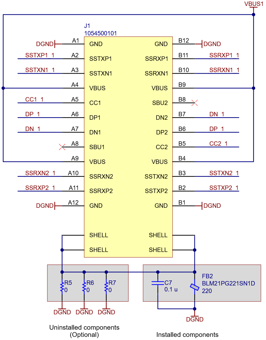
USB Connector Shell Termination
The shells of the USB-C connectors are terminated to circuit ground using a 0.1-uF capacitor in parallel with a 220-ohm ferrite bead. Three uninstalled zero-ohm resistors on each connector allow optional direct (DC) connection of the shell to circuit ground if desired.
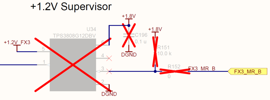
Configure USB Interface for Manual Reset
If manual reset of the USB interface from the FPGA is required some optional components must be added to the board. All of the normally DNP parts in this schematic snippet will need to be added. The FX3_MR_B signal is connected to pin W24.
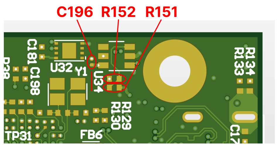
The component footprints can be found on the bottom of the PCB, near the U34 silk screen marking. Components without silkscreen designators are labeled below.