Providing VIO Externally
The XEM8310 is designed to support programmable VIO using on-board switching regulators as described in the Expansion Connectors and Device Settings sections of this documentation.
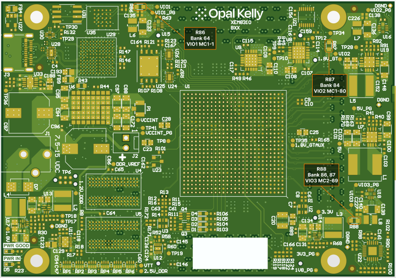
If your application requires that you provide these supplies from your peripheral design, the rework illustrated below will be required to safely disconnect the on-board regulator(s) from these VIO. After this rework is applied, you will be able to provide VIO1, VIO2 and/or VIO3 through the expansion connector from your peripheral, subject to the limitations of the FPGA itself.
By default, 0-Ω jumper resistors have been installed that attach each VCCO bank to the on board VIO supply. If you intend to supply power to a particular I/O bank externally, you MUST remove the appropriate resistor first. Power can then be supplied through the expansion connectors.
Enabling of external VIO rails should be sequenced after +1.8V (Available on MC1) is fully powered.
The table below lists details for user-supplied I/O bank voltages
| I/O BANK | VIO | VOLTAGE RANGE | EXPANSION PINS | JUMPER RESISTOR |
|---|---|---|---|---|
| 64 | VIO1 | 0.95 – 1.90 V | MC1-1 | R86 |
| 84 | VIO2 | 1.14 – 3.40 V | MC1-80 | R87 |
| 86, 87 | VIO3 | 1.14 – 3.40 V | MC2-69 | R88 |