USB 3.0 Host Interface
There are 41 signals that connect the on-board USB microcontroller to the FPGA. These signals comprise the host interface on the FPGA and are used for configuration downloads. After configuration, these signals are used to allow FrontPanel communication with the FPGA.
If the FrontPanel okHost module is instantiated in your design, you must map the interface pins to specific pin locations using Xilinx LOC constraints. This may be done using the Xilinx constraints editor or specifying the constraints manually in a text file. Please see the sample projects included with your FrontPanel installation for examples.
Host Interface Clock
The okHost module provides a 100.8 MHz clock to your design that is synchronous to the host interface. This clock must be used for all pipe interfaces unless clock synchronizers (e.g. asynchronous FIFOs) are used to cross a clock boundary to another system clock.
Reset Profile RESET
Pin G22 of the FPGA is an active-high RESET signal from the host interface. This signal is asserted when configuration download begins and is deasserted during the execution of the Reset Profile. For more information on the timing of this deassertion event, see the FrontPanel User’s Manual.
USB Host Interface Documentation
The USB host interface includes Opal Kelly’s proprietary microcontroller firmware and proprietary HDL modules. Opal Kelly does not provide schematics or documentation for the inner workings of this interface. Everything you need to know to deploy the host interface in your application is documented in the FrontPanel User’s Manual. As part of the FrontPanel SDK, several examples are included for each board. Pins should be used to generate a reference constraints file for your HDL design.
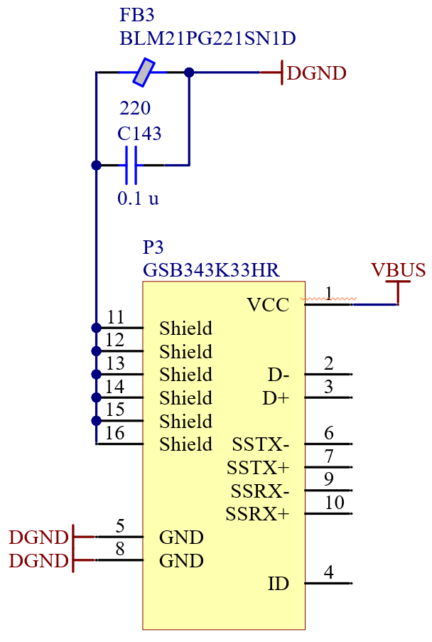
USB Connector Shell Termination
The shell of the USB Micro-B connector is terminated to circuit ground using a 0.1-uF capacitor in parallel with a 220-ohm ferrite bead.