Gigabit Transceivers
Access to eight high-speed serial transceiver pairs (8 Rx and 8 Tx) corresponding to GTX tiles 115 and 116 on the FPGA are available on the FMC expansion connector. MGTREFCLK0 of tile 115 and MGTREFCLK0 of tile 116 are also routed to FMC. MGTREFCLK1 of tile 115 is connected to a low-jitter 100 MHz LVDS oscillator.
AC-Coupling
0.1μF AC-coupling capacitors are installed between the FMC connector and the FPGA for all MGTREFCLK signals.
AC-coupling capacitors are not installed for any of the GTP transmit or receive pairs. If AC-coupling is desired or required for the serial application, they should be installed on the peripheral side (your board).
IBERT Configuration
Xilinx provides the IBERT tool to test and experiment with gigabit transceivers. The settings below are compatible with the XEM7350 using Vivado 2013.4:
| PROTOCOL DEFINITION | ||
|---|---|---|
| Silicon Version | General ES / Production | |
| Protocol | Custom 1 | |
| Line Rate | 6.6 Gbps | |
| Data Width | 32 | |
| Ref Clk | 100.000 MHz | |
| Quad Count | 2 | |
| Quad PLL | Checked | |
| PROTOCOL SELECTION | ||
| GTX Location | QUAD_115 | QUAD_116 |
| RefClk Selection | MGTREFCLK1_115 | MGTREFCLK1_116 |
| TXUSRCLK Source | Channel 0 | Channel 0 |
| CLOCK SETTINGS | ||
| Add RXOUTCLK Probes | Unchecked | |
| Clock Type | System Clock | |
| Source | External | |
| I/O Standard | LVDS | |
| P Package Pin | AC4 | |
| N Package Pin | AC3 | |
| Frequency | 200 MHz | |
| Enable DIFF Term. | Unchecked |
Gigabit Transceiver IBERT Performance
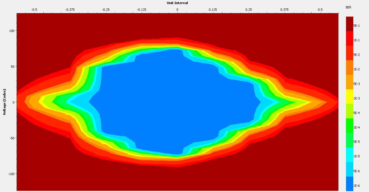
Xilinx’s IBERT tool enables an automated self-measurement of a GTP channel’s eye diagram when used in a loopback mode. Eye diagrams for three different speeds were captured using this tool on an FMC loopback peripheral. While results may vary, these were rather typical captures and actually represent the worst case capture over all channels for the respective rates.
Note that in loopback modes, it is often helpful to disable the GBT DFE (decision feedback equalizer) to avoid over-compensation. In these test cases, the DFE has been disabled.
3.3 Gbps / XEM7350-K70T
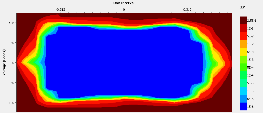
6.6 Gbps / XEM7350-K70T
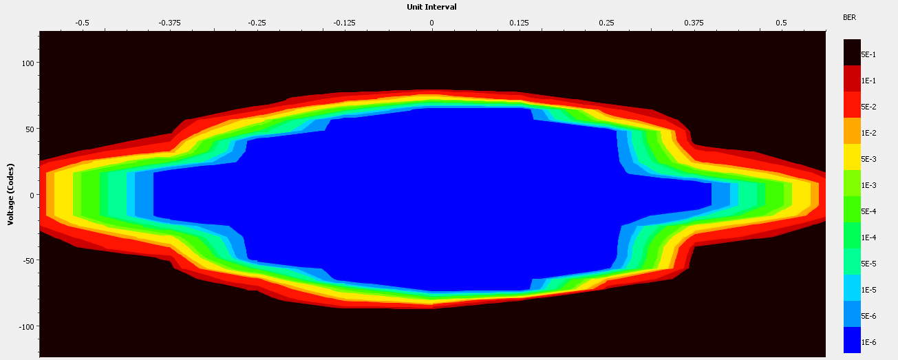
8.0 Gbps / XEM7350-K160T