System Design
okHost is one component in a larger system. Three pieces are in play: okHost the component (documented on okHost Core), the FrontPanel host software (the FrontPanel API), and the AXI endpoint IP you attach.
Interface Routing
okHost presents a single Manager on each memory-mapped interface (m_axi and m_axil) and a single port in each stream direction (m_axis and s_axis). Reaching more than one endpoint is a routing problem you solve with an AXI interconnect between okHost and your endpoints.
Memory-mapped interfaces (m_axi, m_axil). To reach more than one Subordinate, place an AXI interconnect between okHost and your Subordinates and give each Subordinate a base address. Those base addresses are your memory map, and the host reaches any register by its absolute address, the base plus the register offset. An address that maps to no Subordinate is reported to the host as AXIDecodeError, covered under Error Handling. okHost reserves no address space of its own, as covered under The Address Map Is Yours. Choose the interconnect by flow, an AXI SmartConnect in a Block Design or standalone AXI cores in pure RTL, under AXI Libraries and IP.
Stream interfaces (m_axis, s_axis). okHost presents one stream per direction with no TID or TDEST, as under AXI-Stream Specifics. To multiplex several logical streams, place an AXI4-Stream Interconnect (PG085) between okHost and your stream endpoints. The two directions are different problems. A demux routes one m_axis Manager to several stream Subordinates. Because okHost drives no Manager TDEST, steer it over AXI-Lite by writing the interconnect’s control registers over m_axil to connect an input to an output. A mux combines several stream Managers into one s_axis Subordinate. With a single destination it is an arbitration problem. Choose an arbiter mode, and note that a fixed-priority scheme can starve a low-priority port. See PG085.
For a trivial case, you can mux or demux in your own RTL with a header word, or carry an extra channel over AXI-Full or AXI-Lite. The AXI4-Stream Interconnect is the standard path.
Crossing Clock Domains
okHost’s AXI interfaces are synchronous to aclk, whose frequency is fixed at build time, and its three aresetn outputs are synchronous to aclk as well. Your own logic, and most AMD IP such as a DDR or MIG controller or your processing pipeline, usually runs on a different clock. Crossing from okHost’s aclk domain into yours is therefore the common case. Cross both the data path and the reset.
Data path. Place an AXI Clock Converter (for AXI-Full or AXI-Lite) or an AXI4-Stream Clock Converter (for streams) between okHost and your logic. An AXI SmartConnect clock-converts as part of its job, so on the memory-mapped side it can serve as both interconnect and clock converter. See AXI Libraries and IP.
Reset. Synchronize the reset with AMD’s Processor System Reset core (proc_sys_reset), clocked by your target clock. It holds reset for the same 16 cycles okHost itself uses. On the memory-mapped side, a SmartConnect can absorb this for you.
As a worked reference, the RAMTester sample runs okHost’s m_axi on aclk through an AXI SmartConnect that clock-converts into the DDR4 controller’s UI clock domain, with a Processor System Reset core clocked by the DDR4 UI clock producing the synchronized aresetn for the DDR4 AXI Subordinate.
Idle Gaps and FIFO Sizing
This section applies to USB devices only. okHost does not move data continuously. It delivers in chunks with brief idle gaps between them, an artifact of the USB microcontroller that bridges the FPGA to the USB link rather than of the USB standard. The cause and the ballpark figures are documented under Idle Gaps on the USB Transport page. Designing for those gaps differs by interface.
AXI-Full is almost always a non-issue. A memory Subordinate waits through a gap. The one case that matters is sharing a Subordinate through an interconnect with other Managers. An idle gap in the middle of okHost’s transfer keeps the shared Subordinate allocated to okHost, head-of-line blocking the other Managers. The fix is to enable the interconnect’s packet mode, which buffers each burst and hands it to the shared Subordinate gap-free, sized to hold one of okHost’s bursts (your burst length). The IP options are under AXI Libraries and IP.
AXI-Stream is the case to check for a fixed-rate endpoint that cannot pause, such as a free-running ADC on s_axis or a continuous DAC or pipeline on m_axis. A too-small buffer over- or underflows with no error from okHost, so this is worth getting right. If your endpoint can stall instead, the gaps are ordinary backpressure and you can skip this.
The fix is a FIFO between your endpoint and okHost that absorbs the gaps. If your endpoint crosses into its own clock domain, the AXI4-Stream Data FIFO you use for that crossing can be a dual-purpose buffer, handling both the clock-domain crossing and the gaps. Give it enough depth, and do not add a second. If it runs in aclk with no crossing, add an AXI4-Stream Data FIFO.
Size it from the depth-versus-margin model. A gap slides the FIFO fill level toward empty or full by about one gap’s worth (about 160 words, derived under Idle Gaps). The level recovers only if okHost moves data faster than your endpoint, and that extra speed is the margin. Depth is approximately one gap divided by the margin. Two natural operating points bracket the choice.
| Strategy | okHost sustained rate | FIFO depth |
|---|---|---|
| Speed | ~2x your stream rate | ~256 words (~one gap); the level returns within a gap |
| Utilization | ~1.1x your stream rate | ~2K words (~ten gaps); the level returns slowly |
| Any point | (1 + m)x your stream rate | ~one gap / m |
Round the depth up to a power of two. If you run okHost at or below your stream’s rate, there is no margin and no depth keeps the FIFO clear. For a host-to-FPGA stream, pre-fill the FIFO before you start the sink. Wire the FIFO’s overflow or underflow flag to a status register, so an undersized buffer is reported rather than silently corrupting data.
Integrating okHost
Bringing okHost into your own design follows a design-agnostic sequence. The mechanical get-the-sources and build steps are on Getting Started. In a Block Design, you add okHost as the FrontPanel Subsystem IP rather than instantiating the .veo; see the IPI Block Designer guide.
- Get okHost. Choose the board and bandwidth mode, using Bandwidth Modes for the Up and Down figures, then bring okHost in by the SDK or IP Core path. The delivered files are on Delivery and Files; the step-by-step build is on Getting Started.
- Instantiate okHost from the
.veo, described under Instantiation Parameters. Bring the host-interface pins to your top level and letokHost.xdcconstrain them. - Clock.
aclkis an output. Run your AXI-side logic onaclk, or cross into your own clock domain with a Clock Converter, as under Crossing Clock Domains. Do not driveaclk. - Resets and start-up gating. Connect each of the three active-low reset outputs to its interface’s logic, and synchronize into another domain if needed; see Crossing Clock Domains. Hold your AXI-side logic in reset until
board_readyis high, so no traffic starts before board bring-up completes, as under Board Ready and DNA Outputs. - Connect your AXI. Wire
m_axil_*to your control and status registers,m_axi_*to your memory-mapped or DMA space, and the AXI-Stream ports to your stream endpoints, minding the direction. Honor the tie-offs okHost drives and do not wire the signals okHost omits, listed under Signals okHost Omits. To reach more than one Subordinate, add an AXI interconnect, as under Interface Routing and AXI Libraries and IP; for multiple streams, an AXI4-Stream Interconnect. - Constraints and board settings. Add
okHost.xdc, and apply any per-board project settings from Board-Specific Build Notes. - Build. Synthesize, implement, and write the bitstream. The worked steps are on Build the PerfTest Example.
- Smoke-test the board. Confirm the board and FrontPanel install are healthy, independent of your gateware, with the board smoke test on Troubleshooting & Debugging.
- Configure the FPGA. Load your bitstream onto the board.
- Exercise your design. Drive your registers and interfaces from your own host application, written against the FrontPanel API.
For a full runnable instance, read the PerfTest build on Getting Started. It is this skeleton with a real DUT attached.
AXI Libraries and IP
okHost is a standard AXI Manager, so you build the rest of your AXI side from standard AXI building blocks. You will almost always need at least a clock-domain crossing, and an interconnect if you have more than one Subordinate.
AMD AXI infrastructure IP ships with Vivado and needs no extra license.
For a memory-mapped fabric on m_axi or m_axil, do not use the monolithic AXI Interconnect IP; it is retired in favor of AXI SmartConnect. Instead:
- In a Block Design, use AXI SmartConnect (PG247), AMD’s recommended soft interconnect, which auto-inserts clock-domain crossing and data-width conversion. It is IP Integrator only.
- In pure RTL, compose from standalone cores: AXI Crossbar to route one Manager to many Subordinates, AXI Clock Converter to cross
aclk, AXI Data Width Converter, AXI Data FIFO for buffering and packet mode, and AXI Register Slice (PG373) or AXI Protocol Converter as needed.
To enable packet mode for the AXI-Full shared-Subordinate case under Idle Gaps and FIFO Sizing, enable it on the SmartConnect (PG247) or a standalone AXI Data FIFO.
For streams, the AXI4-Stream Infrastructure IP Suite (PG085) provides the AXI4-Stream Interconnect and Switch (the stream demux and mux, as under Interface Routing) plus stream clock, width, and FIFO cores.
The Processor System Reset core (proc_sys_reset) synchronizes a reset into a target clock domain, as under Crossing Clock Domains.
For control and status register blocks, a CSR generator turns a register-map description into a synthesizable AXI4-Lite block; see Building Your CSR below for how to start and when to graduate to one.
Structuring Your AXI Core
We recommend structuring the AXI Subordinate core you attach to okHost as three modules, though okHost does not require it: a top wrapper <core>_core, a control and status register block <core>_csr that is an AXI-Lite Subordinate, and the functional logic <core>_logic. All of our example cores follow this pattern.

The wrapper <core>_core exposes the Subordinate ports and instantiates and wires the CSR and logic modules; it carries no functionality of its own. The <core>_csr block is an AXI-Lite Subordinate holding the address-mapped registers, with only two boundaries: AXI-Lite and a bundle of named wires. The <core>_logic module is your application logic, which carries AXI-Full or AXI-Stream and has no AXI-Lite knowledge.
This structure buys three things. The logic never touches a bus address, which keeps it clean. The CSR is swappable, so you can replace <core>_csr without touching the logic or the wrapper. And it enables a driver layer on the host. A class wraps raw register reads and writes behind domain operations such as counter.increment() or des.encrypt(...), holding the register map in one place that mirrors the gateware _csr.
In the Counters sample, the driver holds the register map in one place, and each method performs the AXI-Lite write or read:
// AXICountersDriver.ts (excerpt): the driver wraps the CSR
const TRIG_CTRL = {
  address: 0x0040,
  RESET:     0x01,  // [0] WO - Reset counter2
  INCREMENT: 0x02,  // [1] WO - Increment counter2
  DECREMENT: 0x04,  // [2] WO - Decrement counter2
} as const;

class Counter2 {
  constructor(private readonly port: IFPGADataPortAXI) {}
  async reset():     Promise<void> { await this.port.axiLite.write(TRIG_CTRL.address, TRIG_CTRL.RESET); }
  async increment(): Promise<void> { await this.port.axiLite.write(TRIG_CTRL.address, TRIG_CTRL.INCREMENT); }
  async decrement(): Promise<void> { await this.port.axiLite.write(TRIG_CTRL.address, TRIG_CTRL.DECREMENT); }
}Code language: JavaScript (javascript)
The gateware counters_csr block is the other half of the parallel. It holds the same register at the same address, and a write to TRIG_CTRL lands in trig_ctrl_reg, which clears every cycle so each set bit pulses for one cycle:
// counters_csr.v (excerpt): the register the driver writes
localparam [63:0] CSR_ADDR_TRIG_CTRL = 64'h0000_0040;

CSR_ADDR_TRIG_CTRL: trig_ctrl_reg <= s_axil_wdata;  // a write to 0x0040 lands here

assign reset2 = trig_ctrl_reg[0];  // RESET,     0x01
assign up2    = trig_ctrl_reg[1];  // INCREMENT, 0x02
assign down2  = trig_ctrl_reg[2];  // DECREMENT, 0x04Code language: HTML, XML (xml)
The host TRIG_CTRL.RESET bit and the gateware trig_ctrl_reg[0] are the same bit at address 0x0040.
Our example cores follow the pattern and escalate in scope: Counters uses AXI-Lite only, DES adds AXI-Stream, and PerfTest adds AXI-Full and AXI-Stream. Each ships gateware and a matching driver.
Building Your CSR
Do not hand-write the AXI-Lite decode. Start from our sample CSR, a hand-written block that is the AXI analog of the Classic WireIn, WireOut, TriggerIn, and TriggerOut endpoints, shipped in Counters, DES, and PerfTest. Graduate to a CSR generator for a larger or evolving map. Describe the map once, generate a synthesizable AXI4-Lite block, wire m_axil_* to it, and get the endpoint behaviors and matching C headers and documentation for free. Because the structure isolates the CSR, you swap only <core>_csr and regenerate the matching driver.
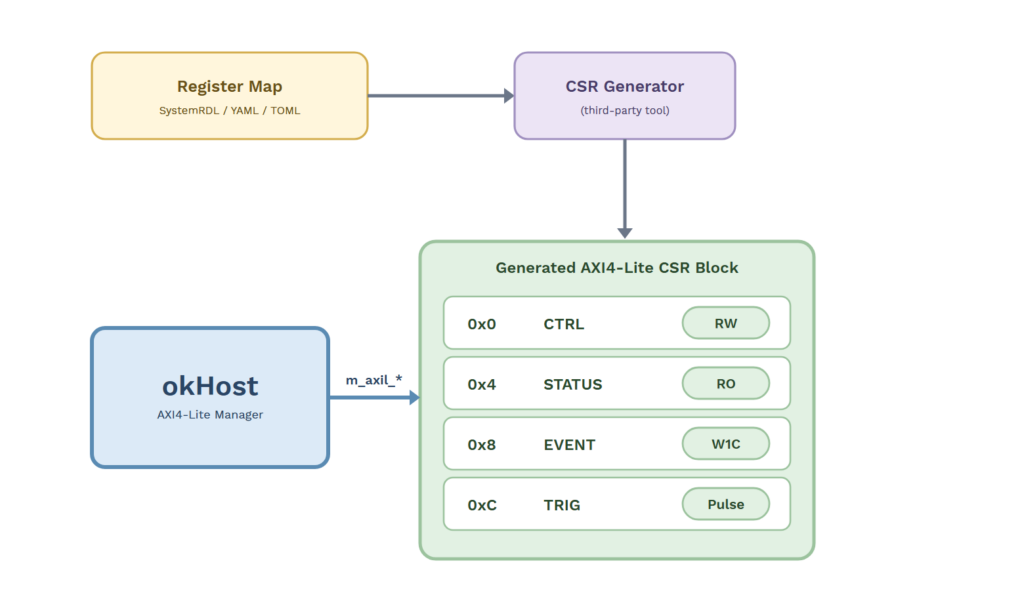
Several good open-source generators exist, among them PeakRDL-regblock, Corsair, RgGen, and hdl-registers.
Diagnosing with the Counts
Every okHost AXI operation that moves data returns counts. A completed operation returns the full count; an operation that times out returns the count reached at the timeout. The count is your first debug tool, before any hardware instrumentation.
What each call returns, including the transaction count that an AXI-Full write or an AXI-Lite bulk write adds, is documented under Counts Returned.
On an AXI-Full or AXI-Lite write, the byte count and the transaction count can diverge, and the split localizes the fault. The byte count tracks how much W data your Subordinate accepted; the transaction count tracks how many BRESP responses it returned. A full byte count with a zero or low transaction count and a timeout means your Subordinate took the data but never responded on the B channel. A low byte count means the write stalled before all its data was accepted. On a read or a stream, the byte count is how far the operation got, and the 0xE7 fill marks the unfilled region.
This first-pass triage localizes the failure, whether on the B channel, the AW or W handshake, or the read data, before you touch hardware. Then instrument the wire:
- Add an AMD ILA on the okHost-to-Subordinate channels, triggered on the implicated handshake or response.
- Add an AMD AXI Protocol Checker IP to flag protocol violations live.
- Compare against PerfTest, our known-good design, to isolate whether the issue is your logic or elsewhere.
The gateware-relevant error codes and what they point at are on Error Handling.
See Also
- okHost Core: the component facts (interfaces, omitted signals and constants, behaviors, per-interface specifics, ports, parameters, status, and resets).
- Getting Started: the mechanical get-the-sources, build, and load steps. The delivered files are on Delivery and Files.
- USB Transport: the bandwidth table, the idle-gap cause, and footprint.
- Troubleshooting & Debugging: error-code meanings, troubleshooting, and support.
- Migration Guide: CSR registers as the AXI replacement for Classic Wire and Trigger endpoints.
- FrontPanel API: drive okHost from host software.