USB 2.0 Host Interface
There are 27 pins that connect the on-board USB microcontroller to the FPGA. These pins comprise the host interface on the FPGA and are used for configuration downloads. After configuration, these pins are used to allow FrontPanel communication with the FPGA.
If the FrontPanel okHostInterface module is instantiated in your design, you must map the interface pins to specific pin locations using Xilinx LOC constraints. This may be done using the Xilinx constraints editor or specifying the constraints manually in a text file. Please see the sample projects included with your FrontPanel installation for examples.
Pins can be used to generate a reference constraints file for your HDL design.
MUXSEL
MUXSEL is a signal on the XEM7001 which selects the signal path to the FPGA programming signals D0 and CCLK. When low (deasserted), the FPGA and USB microcontroller are connected. When high (asserted), the FPGA and Flash are connected.
In normal USB-programmed operation, JP5 is positioned at “USB” and pulls MUXSEL low, connecting the FPGA and USB microcontroller at all times. This allows USB-based programming of the FPGA and subsequent USB communication with the FPGA design after configuration.
In order to allow the Flash to configure the FPGA, JP5 is positioned at “PROM.” In order to deassert MUXSEL post-configuration, your design must deassert MUXSEL. This allows the FPGA design to properly startup and allows for communication over USB even after the Flash has configured it.
The end result is that your FPGA design should always tie HI_MUXSEL to 0. This is the case regardless of how the design was configured (via Flash or USB). For example, in Verilog:
assign hi_muxsel = 1'b0;USB Connector Shell Termination
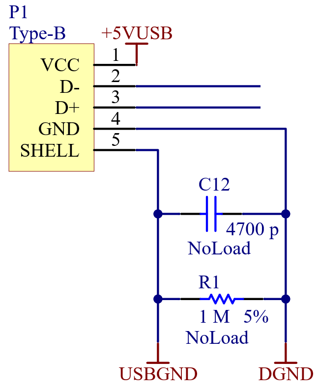
The shell of the USB Type-B connector is left unterminated (floating) on the XEM7001. Two uninstalled components allow optional termination to circuit ground using a 4700-pF capacitor in parallel with a 1-MΩ resistor. Component values may be modified as necessary according to the application requirements.