BRKD-ACV Breakout Board
The BRKD-ACV is a basic “breakout board” / reference design which can be used to evaluate or transition to the FOMD-ACV. It includes the following features:
- +5 VDC input connector with over-voltage protection
- Four DIP-programmable voltage regulators for VCCIO1, VCCIO2, VCCPD1, and VCCPD2
- Two 2×10 2-mm header locations
- Four 2×20 2-mm header locations
- Four Digilent PMOD connectors
- Two Pushbuttons
- JTAG Connector
Please visit the Pins reference for the FOMD-ACV for pin mapping details. Full Altium schematics and PCB layout are available through Pins Downloads.
Voltage Regulators
PWR1 (S3) controls VCCIO1 and VCCPD1. PWR2 (S4) controls VCCIO2 and VCCPD2.
Switches 1 – 6 of each DIP switch control VCCIOx. When in the ON location, they contribute the corresponding voltage to the total. When in the OFF location, they contribute 0mV to the total. 500mV is always contributed to the total. Therefore, the output voltage is 500mV plus the sum of all ON switches. For example, to select 2.5v, set the switches accordingly:
- 4, 6 = ON
- 1, 2, 3, 5 = OFF
- Output = 500mV + 400mV + 1600mV = 2.5V
| SWITCH | OFF | ON |
|---|---|---|
| 1 | 0mV | 50mV |
| 2 | 0mV | 100mV |
| 3 | 0mV | 200mV |
| 4 | 0mV | 400mV |
| 5 | 0mV | 800mV |
| 6 | 0mV | 1600mV |
| 7 | VCCPDx = 2.5v | VCCPDx = 3.3v |
| 8 | Disabled | Enabled |
Note: Switch 4 is incorrectly labeled as “0.5V” in the PCB silkscreen.
FPGA Configuration Mode Select
Ten resistors are used to set the value of the five MSEL configuration pin select pins on the FPGA. The default configuration of these resistors is shown below. The yellow entries are not loaded in the factory default configuration. The existing resistors may be removed and the opposing resistors loaded to change the state of the configuration mode. The default selects Active-Serial with Fast Power-On-Reset (MSEL4-0 = 10010).
| MSEL | PULL-UP (VCCPGM) | PULL-DOWN (DGND) |
|---|---|---|
| MSEL4 | R1, 0Ω | R8, 10kΩ |
| MSEL3 | R2, 10kΩ | R9, 0Ω |
| MSEL2 | R3, 10kΩ | R10, 0Ω |
| MSEL1 | R4, 0Ω | R11, 10kΩ |
| MSEL0 | R5, 10kΩ | R12, 0Ω |
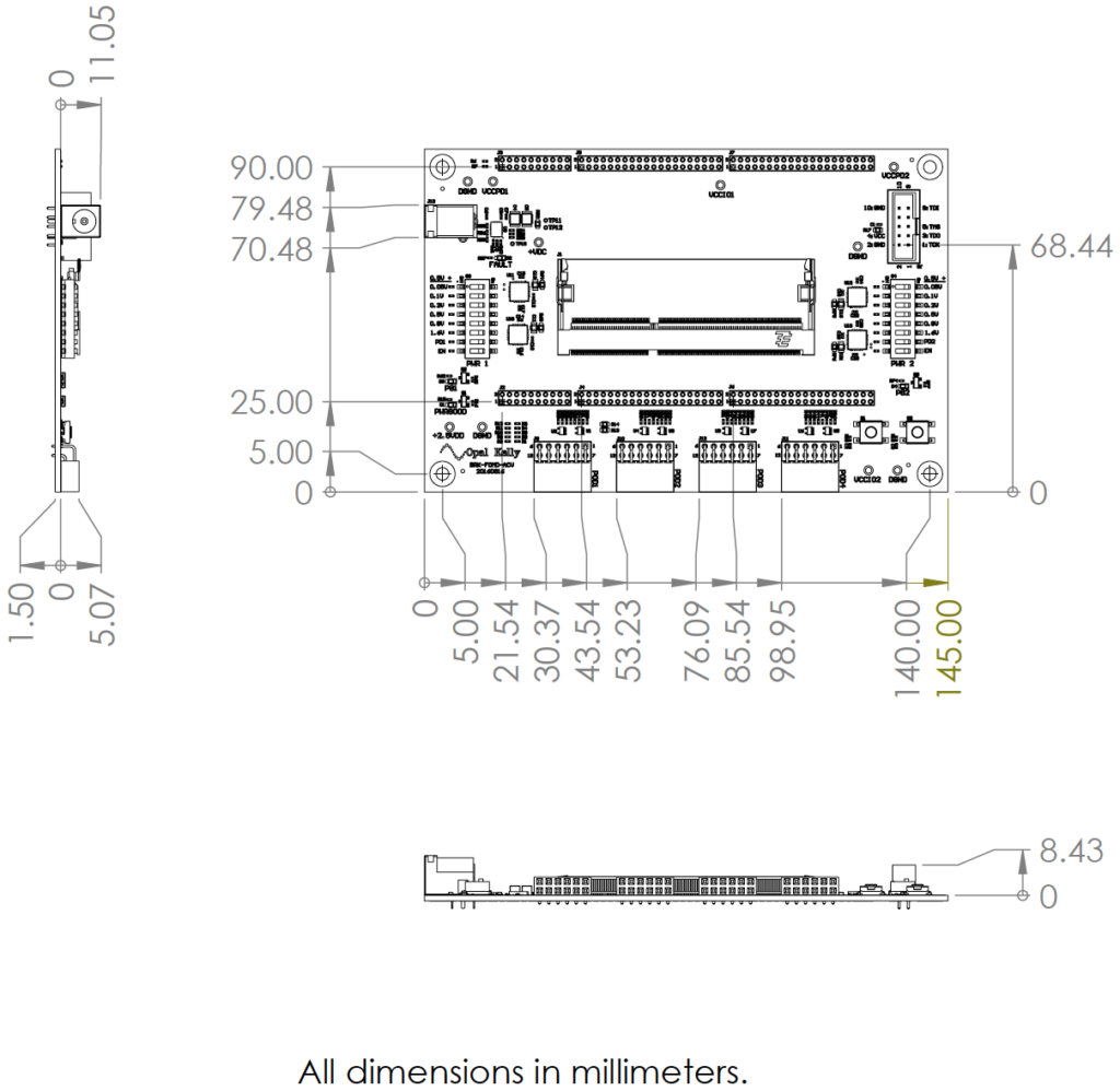
Mechanical Drawing