Mechanical Design
Peripheral Connector Placement
Peripheral designers should consider the impact of connector placement location. Carriers may have side-by-side port spacing as small as 2 mm (to support double-wide peripherals). Right-angle or edge-launch connectors placed along the sides of the peripheral could lead to interference with adjacently-mounted peripherals on the carrier. The best location for such connectors is along the board edge opposite the Samtec board-to-board connector. The use of vertical-launch connectors is also encouraged where feasible.
Peripheral Mechanical Support
Peripherals that are large in size or require substantial cabling may benefit from additional mechanical support. This support would be in addition to the board-to-board mounting hardware as described in the SYZYGY specification. Design of such support is beyond the scope of this guide, but may include, for example, a 3D-printed support bracket.
Peripheral Mounting Hardware
In many cases, the Samtec board-to-board connectors provide sufficient mechanical support between the carrier and peripheral. When a more robust mechanical connection is needed, for example when the peripheral is cabled to an external system, mounting holes provide the option for adding board-to-board standoffs.
The recommended hardware size is M3. Carriers and peripherals should be designed to accommodate this size.
The nominal SYZYGY board-to-board (carrier-to-peripheral) height is 5 mm. The mated height is determined by the Samtec connector placed on the peripheral. Other mated heights are possible. See the SYZYGY specification for more details.
There are many options available for non-custom mounting hardware. The table below lists two potential options.
| Description | Component | Part Num |
|---|---|---|
| Male-to-female 5mm hex standoff with screw and nut | Male-Female Threaded Hex Standoff, 5 mm | McMaster-Carr 93655A401 |
| Phillips screw, 4 mm | McMaster-Carr 92000A113 | |
| Nut | McMaster-Carr 91828A211 | |
| Male-to-female 5mm hex standoff with screw and thumb nut | Male-Female Threaded Hex Standoff, 5 mm | McMaster-Carr 93655A401 |
| Phillips screw, 3 mm | McMaster-Carr 92000A076 | |
| Thumb nut | McMaster-Carr 96445A330 | |
| Male-to-male hex standoff with nuts | Male-male threaded hex standoff, 5 mm | Samtec SO-0515-02-01-01-L |
Cable Mounting Hardware
The nominal standoff height for SYZYGY cables is 0.125″ (3.18 mm). An option for standoff hardware is shown in the table below.
| Description | Component | Part Num |
|---|---|---|
| Male-to-male 0.125″ threaded standoff with nuts | Male-Female Threaded Hex Standoff, 0.125″ | McMaster-Carr 95316A100 |
| Nut | McMaster-Carr 91841A005 |
Status Indicators and PCB Labels
Carrier designers should consider including the following items for usability:
- An LED indicator for each VIO rail to indicate when the rail is active
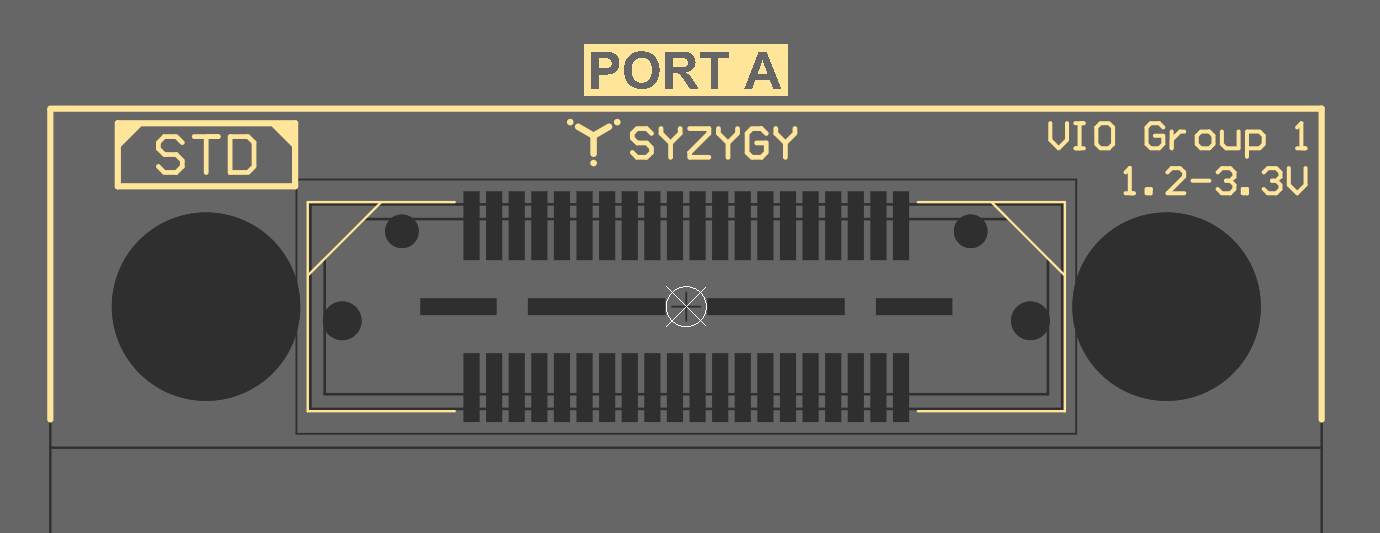
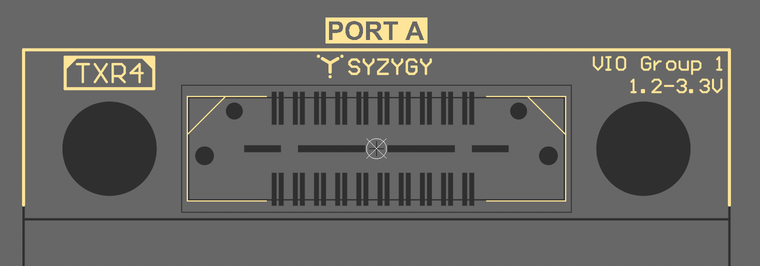
- Silkscreen indicators for each port:
- Port identifier (letter, number, reference designator, etc)
- Port type (standard, TXR2, TXR4)
- VIO group
- Compatible voltage range
Example layouts for port silkscreen are shown below.