Pre-Compliance EMC Testing with Opal Kelly FPGA Development Modules
Introduction
Scope
Electromagnetic compatibility (EMC) is an important consideration for any designer working on a product that is intended for release to customers as all major geographical markets have regulations governing the sale of products that have the potential to generate electromagnetic interference (EMI) or be affected by it. Although regulatory compliance is ultimately a responsibility of the system designer/integrator, the information provided here can help inform the decisions needed to achieve an end product that is compliant with applicable EMC standards. In particular, Opal Kelly integration modules are not considered finished products as defined in the regulatory directives (e.g. CE EMC Directive). Rather, the full system that must be submitted for certification.
This paper provides an overview of some of the factors that affect EMC as well as some background information on some of the regulatory certifications that may be applicable to systems that incorporate Opal Kelly FPGA integration modules.
This paper also presents the results of a “pre-scan” test of Opal Kelly’s XEM7310 and XEM7350 modules using a few different configuration scenarios. While pre-scan measurements such as these are generally not considered a thorough EMC evaluation for certification purposes, they can be helpful to understand some baseline expectations prior to a full test scan.
Acronyms and Definitions
CE – Conformité Européenne. The CE marking certifies conformance to relevant performance standards for products sold within the EEA.
CISPR – Comité International Spécial des Perturbations Radioélectriques, a special committee formed by the IEC to set standards for controlling electromagnetic interference. Standards produced by the committee are typically designated using a two-digit number – for example, CISPR 32 defines the emissions requirements for multimedia equipment.
EMC – Electromagnetic Compatibility, the degree to which an electronic device can operate in a noisy electromagnetic environment without being a source of noise itself.
EEA – European Economic Area, a unified market which combines the member states of the EU (European Union) with the member states of the European Free Trade Association (EFTA). The CE marking applies to products sold in the EEA.
EUT – Equipment Under Test.
FCC – Federal Communications Commission, an agency of the United States government responsible for regulating radio and wire communications, including the control of electromagnetic interference.
IEC – International Electrotechnical Commission, an international standards organization which publishes standards for electronic and related technologies. CISPR is a committee of the IEC.
Integration module – an FPGA-based circuit board module designed to provide an interconnect between a PC and other electronic devices.
PCB – Printed Circuit Board.
Emissions vs Immunity
The field of EMC considers two general types of behavior: emissions and immunity. Emissions are the electromagnetic noise components generated by an electronic device. These noise components may be conducted (noise transmitted along a power cable, for example) or radiated (noise emanating from a vent in an enclosure, for example). Immunity is the degree to which an electronic device can operate in the presence of electromagnetic noise in the environment. Some regulations, such as FCC in the U.S., concern only emissions. Other regulations, such as the CE EMC Directive in the EU, concern both emissions and immunity.
Emissions often present a larger problem than immunity because immunity is self-regulating to a certain extent within the electronics industry (consumers may stop purchasing a product that is susceptible to interference). The focus of this white paper is radiated emissions.
Applicable Certifications and Testing Standards
EMC regulations are generally specific to commercial markets within individual countries or regions. In some cases, a mandatory certification mark must be placed on the equipment to demonstrate conformity before it can be placed on the market or imported. Emissions requirements vary from market to market, but they are often based on common international standards such as those maintained by CISPR.
CE Certification and the EMC Directive
In the EEA, certain types of products are required to display the CE marking. This marking indicates that the product meets applicable health, safety, and environmental standards defined in the CE directives. The EMC Directive, which is one of several directives that may apply to electronic equipment, includes requirements for emissions and immunity.
Assessing conformity to the EMC Directive is the responsibility of the equipment manufacturer, and in many cases it is a self-certification process. Opal Kelly modules are not considered “finished apparatus” as described in the EMC Directive, and are therefore not covered by the directive. A customer’s end application may fall under the scope of the directive, however, and in this case the entire system design must be considered, including external power supplies, cabling, enclosures, etc.
FCC Rules and Regulations
In the U.S., the control of electromagnetic interference is managed by the FCC according to the rules and regulations described in Title 47 (“Telecommunications”) of the Code of Federal Regulations. Specifically, Part 15 of Title 47 applies to radio frequency devices which radiate electromagnetic energy intentionally (Subpart A) or unintentionally (Subpart B). Unlike the CE EMC Directive, FCC rules and regulations include provisions only for emissions – immunity is not currently regulated.
Conformance to applicable FCC regulations is demonstrated in one of two ways:
- Certification – This includes an authorization provided by an FCC-recognized certification body. It is the more rigorous of the two procedures for demonstrating conformance, and it usually applies to intentional radiators and equipment that is likely to cause harmful interference.
- Supplier’s Declaration of Conformity (SDoC) – This is a self-certification process carried out by the equipment manufacturer. It typically applies to equipment which does not radiate intentionally (i.e., devices without radio transmitters).
Other Regional Standards
China
The China Compulsory Certification (CCC) mark is the equivalent of the CE mark in the EU. It is implemented by the China National Certification and Accreditation Administration (CNCA) for the purposes of national security, human health and safety, environmental protection, EMC requirements, etc.
Japan
In Japan, EMC regulations are implemented by the Japan Voluntary Control Council for Interference (VCCI). As the name implies, conformance to VCCI standards is largely voluntary.
Korea
Electronic equipment placed on the market in Korea must bear the Korean Certification (KC) mark. Similar to the CE mark, the KC mark indicates a product meets certain safety and EMC requirements.
Australia and New Zealand
Although Australia and New Zealand have separate, independent governing bodies for regulating EMC, they share a common certification mark known as the Regulatory Compliance Mark, or RCM. In Australia, use of the RCM is governed by the Australian Communications and Media Authority (ACMA). In New Zealand, it is governed by the Radio Spectrum Management group (RSM). The RCM is mandatory for most digital and RF products placed on the Australian and New Zealand markets.
CISPR 32 Test Standard
CISPR 32 is an international standard created by the CISPR special committee of IEC. Initially released in 2012, this standard addresses testing methods and recommended limits for RF emissions from multimedia equipment. CISPR 32 was adopted by the European Union as EN 55032, the test standard used for determining conformity to the CE EMC Directive. The FCC Part 15 test standards also share similarities with CISPR 32 for radiated emissions measurements below 1 GHz.
Two classes of equipment are defined in CSPR 32:
- Class A covers equipment intended to be used primarily in nonresidential environments (i.e., in commercial or industrial environments).
- Class B covers equipment primarily intended to be used in residential environments. Its requirements for emissions limits are more stringent than those used for Class A.
Application-Specific Contributions to EMC Performance
The EMC performance of a system incorporating an Opal Kelly integration module depends on a variety of application-specific characteristics. These may include, for example:
- the characteristics of the data and clock signals,
- the I/O logic standards used on the board,
- how the FPGA logic is utilized,
- the power consumption of the design,
- and any external peripherals connected to the module board.
For a detailed discussion of the types of emissions covered in this section and their mitigation techniques, refer to chapter 12, “Digital Circuit Radiation” in Henry Ott’s book, Electromagnetic Compatibility Engineering (John Wiley & Sons, Inc., 2009).
Sources of Emissions
Emissions from digital electronics arise from two types of electromagnetic radiation: differential mode and common mode. Differential mode radiation results from currents flowing around loops – for a circuit board, these can be modeled as small loop antennas. The extent of this type of emissions is related to the magnitude of current flowing in the loop, the harmonic content of the current, and the loop area. Common mode radiation is a result of parasitics in the circuit, often due to power and signal-carrying cables attached to the system which act as unintentional antennas. This type of emission is related to the magnitude of the common mode current, the harmonic content of the current, and the lengths of the antennas (i.e. cables).
Clock Frequencies and Data Patterns
The radiation from a current loop is typically worst at high frequencies with periodic waveforms. Clocks are therefore critical in determining the overall EMC performance of a system. This includes clocks that originate from circuity on the board (crystal-based clock oscillators, for example), but it also includes clocks created in the FPGA logic. Although the routing on the PCB is fixed, a system designer does have some control over the characteristics of the clocks used in the design. A designer should consider the number of clocks included, the clock frequencies used, and the routing of FPGA clocks off-chip.
One way to reduce the emissions of a clock signal is to use a spread spectrum approach in which the clock frequency is varied slightly over time. This has the effect of spreading out its energy in the frequency domain, therefore reducing the magnitude of its peak emissions. Similarly, the emissions caused by a data pattern that is highly deterministic can be reduced by applying a randomization function to the data. Like clock dithering, this reduces the amplitude of any strong harmonic content and spreads the energy over a wider range in the frequency domain.
Drive Strength, Voltage Standards, and Edge Rates
The I/O buffers on an FPGA can usually be configured for various voltage standards and output drive strengths. At higher drive strengths, a buffer can generate a larger instantaneous current. This allows for faster rise and fall times on a digital signal, but it also has the effect of increasing the amplitudes of the higher-order harmonics in the frequency spectrum of the signal. These high-frequency components can contribute unnecessarily to the emissions of the device. Best practice is to use the smallest drive strength which allows the device to meet its timing requirements. Properly terminating signals where appropriate can also help reduce emissions.
Logic Design, FPGA Utilization, and External Memory Usage
It can be expected that emissions from a module will increase as the percentage utilization of module resources increases. Logic switching causes transient power supply currents, and this can be another source of radiated emission. As processing activity changes, the signature of the emissions may change over time. During active reads from or writes to an external memory device, for example, emissions in a certain frequency range may be significant. These emissions would be related to the activity on the address and data bus lines connected to the memory device.
Power Supplies and Current Consumption
The on-board power supplies include switching components, and these also contribute to the overall emissions. The switching converters used on Opal Kelly modules typically operate at frequencies in the range of 1-5 MHz. Although this frequency range is relatively low compared to the operating frequencies of other circuits on the board, the amplitude of local currents can be high. Emissions from switching power supplies normally increase as current demands increase.
Peripherals and External Connections
Connections to external peripherals can have an impact on the total system emissions. This can include an external circuit board attached via the mezzanine connectors, or any device connected to the module via a cable such as USB. External peripherals can increase the transient current load of the module power supplies, and they can also create common-mode radiation sources due to the additional cabling.
Enclosures
An enclosure can have a large impact on radiated emissions, both positive and negative. A properly designed metal enclosure acts as a faraday cage around the noisy circuitry within, and it includes proper termination of cables and entry points. An improperly designed enclosure can increase emissions due to air vent resonances, coupling of noise to cable shields, and other effects.
Measurement Procedure
Two Opal Kelly integration modules (XEM7310 and XEM7350) were measured for radiated emissions performance according to the CISPR 32 standard. The measurements were performed in a 5-meter RF anechoic chamber at an accredited EMC testing lab. The results presented in section 5 have been extrapolated to represent a measurement distance of 10 meters. Two different mast antennas were used depending on the frequency band of the measurement: 30 MHz to 1 GHz, and 1 to 6 GHz.
The EUT is positioned on a rotating table. The antenna remains at a fixed location in the chamber but moves to different heights relative to the EUT: 0 m, 1 m, 2 m, and 3 m. At each antenna position, the table holding the EUT rotates once, and a frequency plot is captured representing the highest amplitude reading for each frequency bin at any table angle. This is repeated at each antenna height, and the resulting four graphs are composited to show the worst-case emissions amplitude at any table angle and antenna height. This procedure is carried out twice, once for each of two antenna orientations (horizontal and vertical), resulting in two frequency plots for each EUT configuration.
Three test configurations were measured for each EUT:
- Counters – A simple FPGA configuration using minimal resources to achieve a baseline measurement. This sample does not use external memory and has minimal communication with the host. This sample is available from Opal Kelly.
- RAMtest – A relatively complex FPGA configuration stressing both the DDR memory interface and USB interface. Data is streamed at USB 3.0 SuperSpeed data rates through the USB connection to the on-board DRAM. This is representative of a typical high speed data streaming application. This sample is available from Opal Kelly.
- MEMtest – An FPGA-only memory stress test. This configuration stresses only the DDR memory interface with no communication over USB. Data is generated on the FPGA and written to memory then read back. This provides a memory-only baseline.
For configurations requiring an active USB connection to a PC (i.e. RAMtest), ferrite beads were place on the USB cable at the EUT end of the cable. This reduces some of the cable emissions by up to 10 dB, typically only at frequencies of 200 MHz or lower. The computer used for these measurements was a 2013 15″ MacBook Pro running on battery power with no other devices or peripherals attached.
The data represents peak measurements using 120 kHz resolution bandwidth. A more accurate method for determining amplitude is to use a quasi-peak method, but this generally increases the measurement time required. It can be expected that quasi-peak measurements would be approximately 0.5 to 1.0 dB lower than the peak measurements included here.
Measurement Results
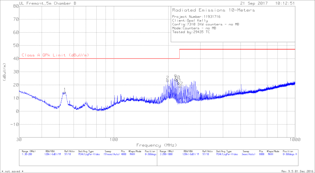
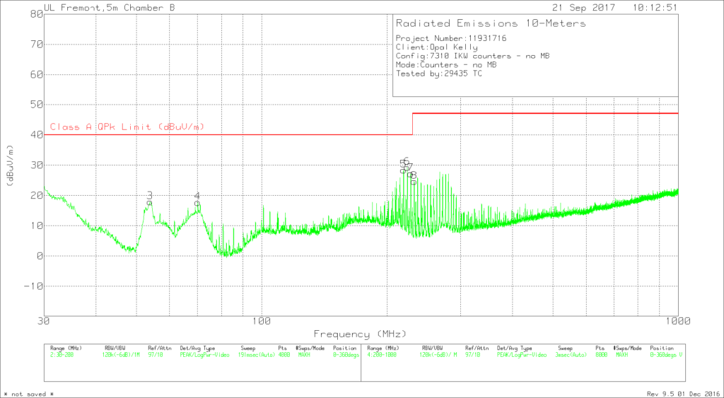
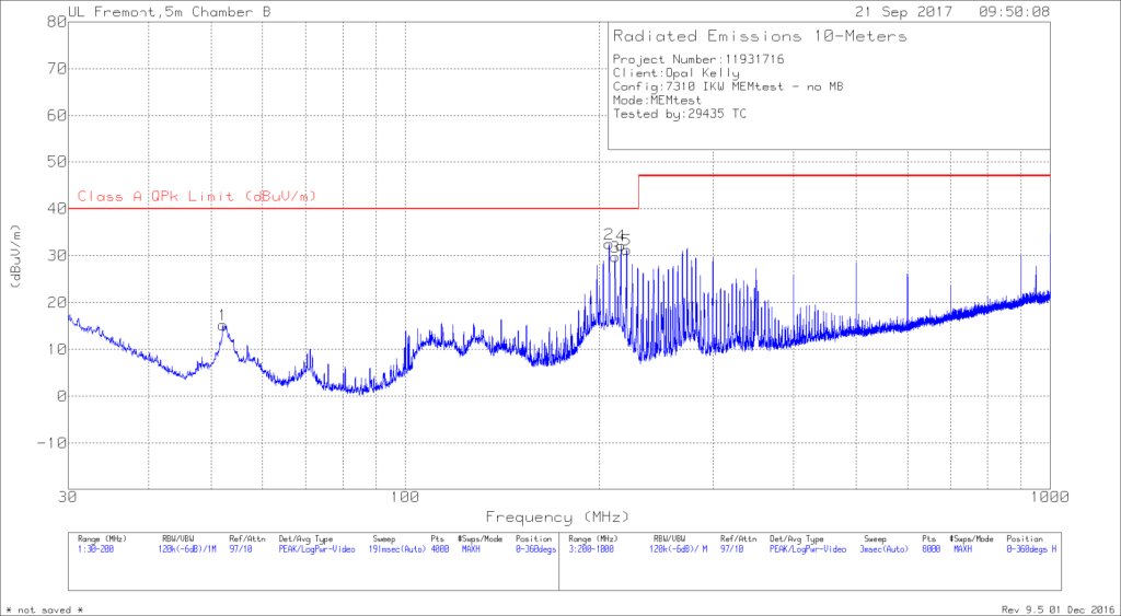
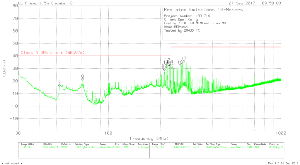
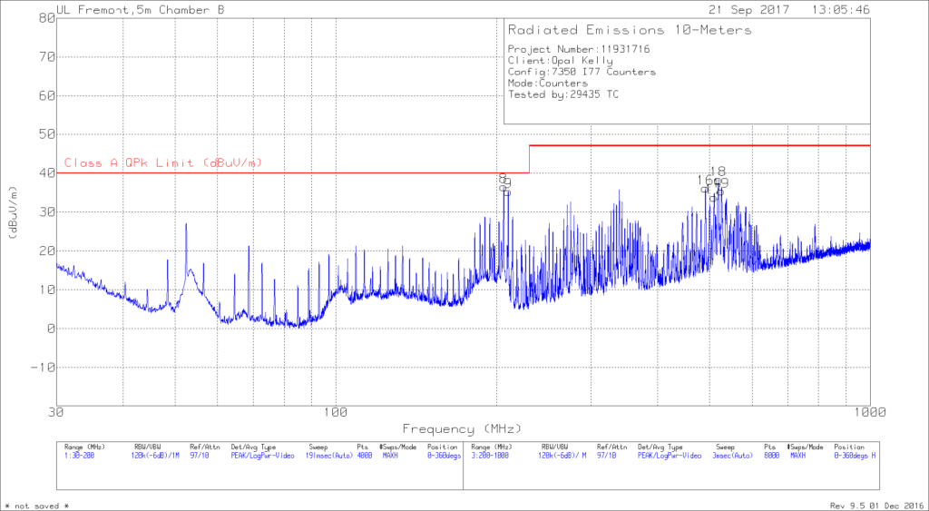
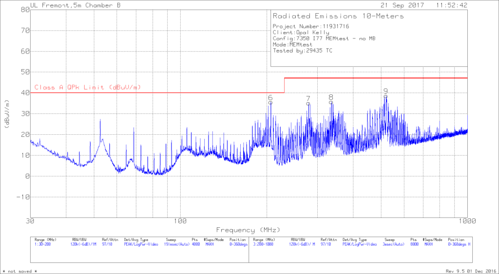
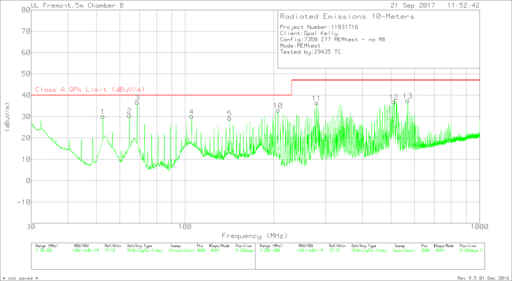
The data shown here represent the measurements described in Section 4. Class A or B limits are included on each graph for reference. (Class A limits are typically 10 dB higher than Class B limits.)
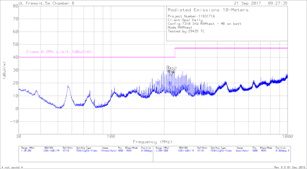
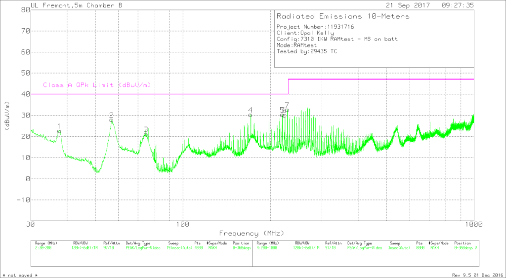
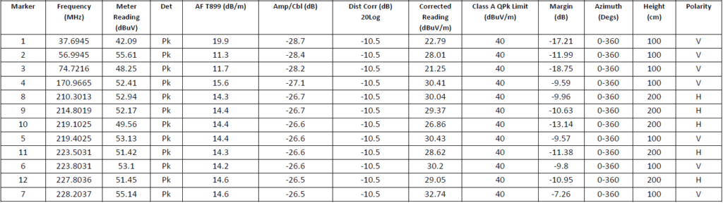
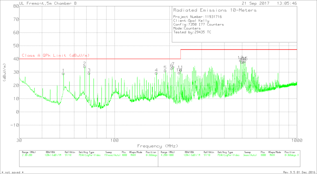
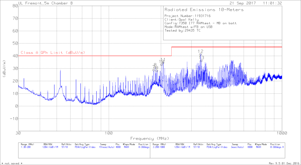
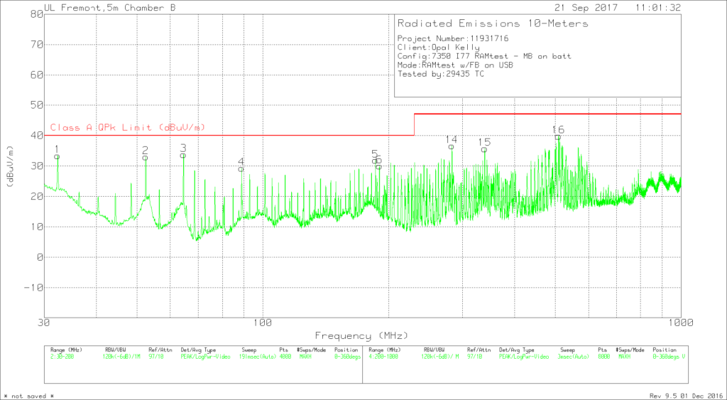
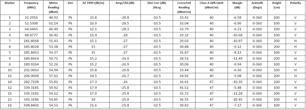
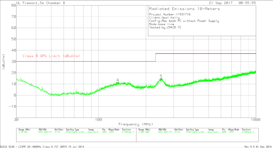
For measurements below 1 GHz, the data represents peak measurements using 120 kHz resolution bandwidth. A more accurate method for determining amplitude is to use a quasi-peak method, but this generally increases the measurement time required. It can be expected that quasi-peak measurements would be approximately 0.5 to 1.0 dB lower than the peak measurements included here. The blue data curve represents horizontal antenna orientation, and the green curve represents vertical antenna orientation.
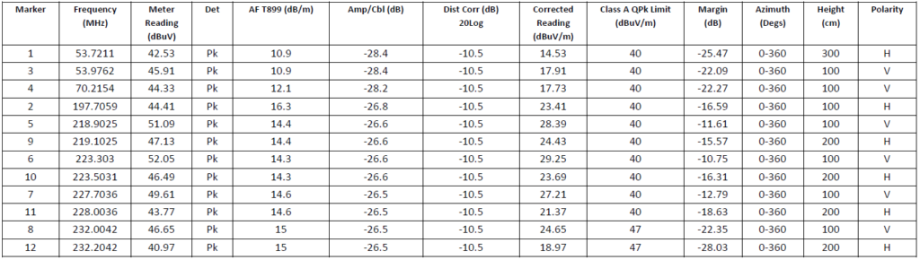
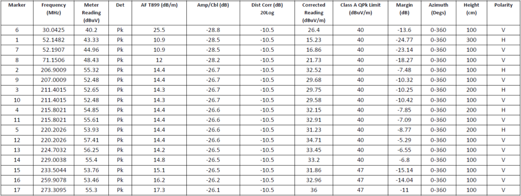
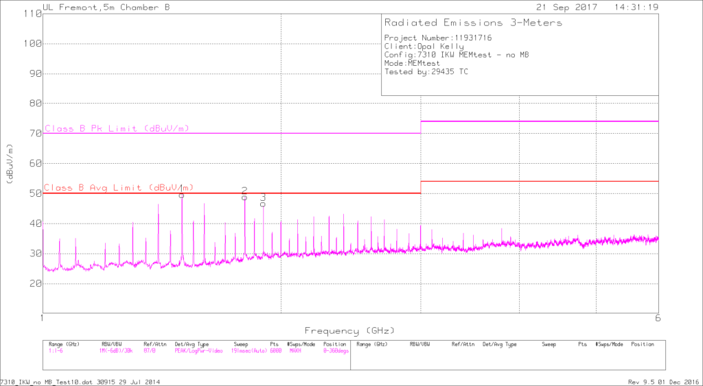
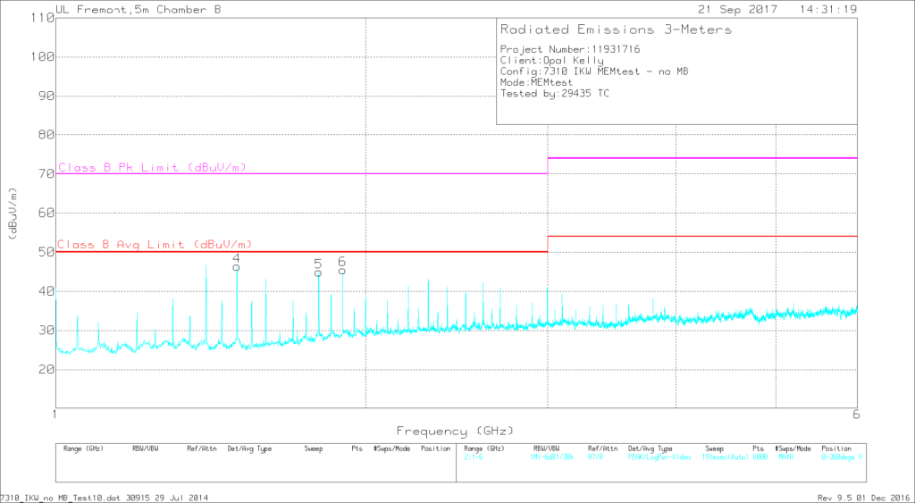
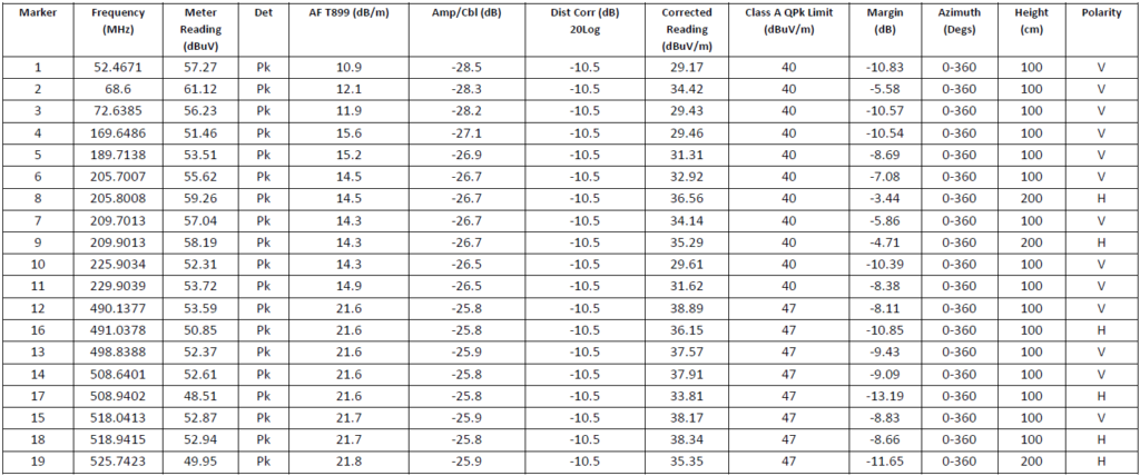
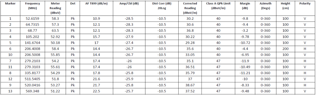
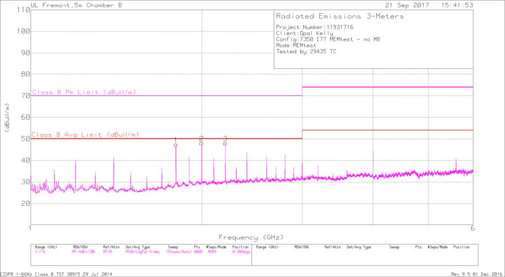
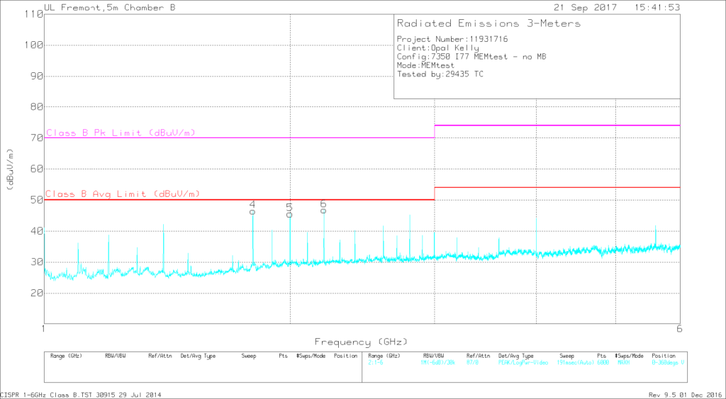
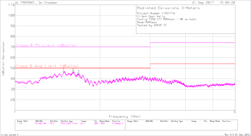
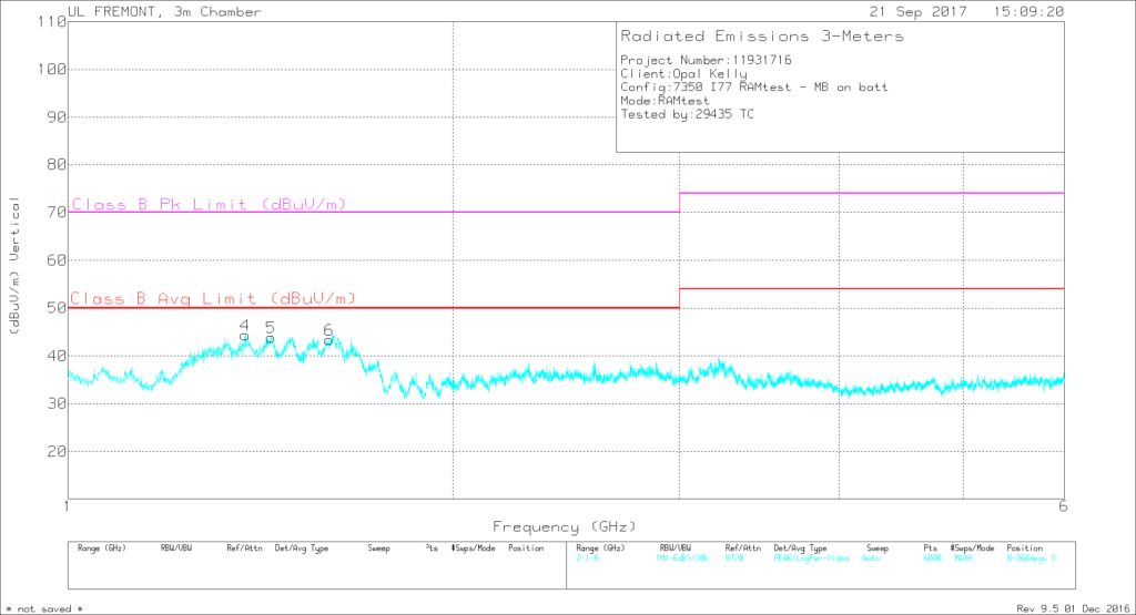
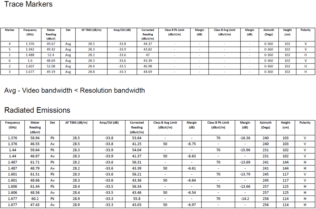
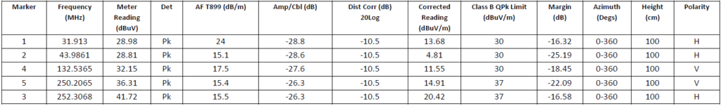
For measurements above 1 GHz, the curves represent the prescan average measurements, corresponding to the “Avg” limits indicated on each graph. (The peak limits on the graphs are shown for reference.) The corresponding tables show the maximized measurements at each frequency marker.
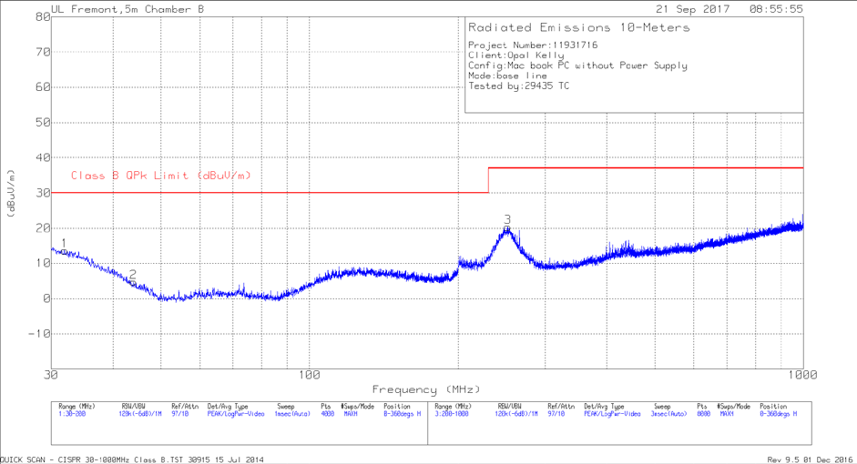
Also included is a baseline measurement of the laptop computer used for the RAMtest configuration. For this measurement, the laptop was running on battery power (no AC power adapter present), and no peripherals or other cabled accessories were attached. The laptop did not have any significant contribution to the total radiated emissions, although some of the emissions can be attributed to the USB cable connecting the laptop to the EUT.
XEM7310 Data
Counters
MEMtest
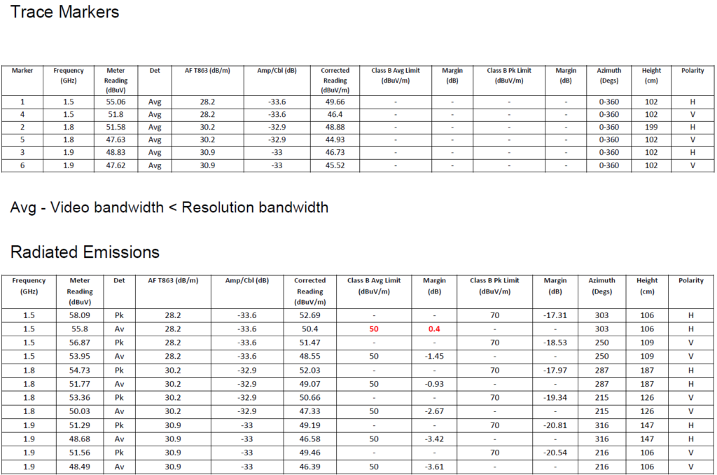
RAMtest
XEM7350 Data
Counters
MEMtest
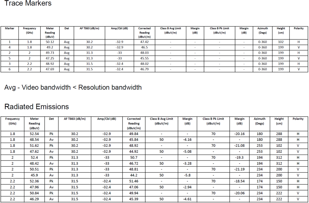
RAMtest
MacBook Baseline
Interpreting the Measurement Data
The measurements show a few notable trends:
- Using Class A limits, the modules tested can generally be considered borderline passing. The passing margins are generally about 6-10 dB, but these results are specific to the example configurations used for these measurements. Other applications may result in higher emissions.
- Configurations that utilize a higher percentage of module resources can have a larger number of emission peaks and higher overall peak amplitudes. On the XEM7310, for example, the MEMtest routine, which exercises the DDR3 memory interface, has emissions in the 200-300 MHz range that are about 6 dB higher than those produced by the Counters configuration.
- Some emissions are present even using low-utilization configurations such as Counters. This is partly due to circuitry on the board which is always active when the module is powered on – for example, clock oscillators, switching power supplies, etc. These emissions can be can be considered to represent the baseline performance of the module.
- Configurations requiring a cabled connection to a computer show more low-frequency emission peaks than stand-alone configurations. In most cases, the RAMtest configuration shows emissions below 200 MHz that can be attributed to the USB connection to the computer. The USB cable used for the measurements included a ferrite placed at the EUT end of the cable. Experiments showed that removing the ferrite increased measured emissions below 200 MHz by as much as 10 dB. Cables and connectors can be a significant source of emissions in an application, and they should be considered as part of the overall electromagnetic compatibility of the system.
- The orientation of the measurement antenna can affect the results. In this case, the vertical orientation generally measures higher peak amplitudes than the horizontal orientation.
Conclusion and Next Steps
The intent of this paper was to provide some background information about electromagnetic compatibility as it pertains to Opal Kelly FPGA integration modules. Every application is different, and the system designer/integrator is responsible for the ultimate compliance of the finished product. The results of the radiated emissions measurements presented in this paper can provide a useful starting point for the development needed to achieve any applicable regulatory compliance.