USB 2.0 Host Interface
There are 26 pins that connect the on-board USB microcontroller to the FPGA. These pins comprise the host interface on the FPGA and are used for configuration downloads. After configuration, these pins are used to allow FrontPanel communication with the FPGA.
If the FrontPanel okHost module is instantiated in your design, you must map the interface pins to specific pin locations using Xilinx LOC constraints. This may be done using the Xilinx constraints editor or specifying the constraints manually in a text file. Please see the sample projects included with your FrontPanel installation for examples.
USB Host Interface Documentation
The USB host interface includes Opal Kelly’s proprietary microcontroller firmware and proprietary HDL modules. Opal Kelly does not provide schematics or documentation for the inner workings of this interface. Everything you need to know to deploy the host interface in your application is documented in the FrontPanel User’s Manual. As part of the FrontPanel SDK, several examples are included for each board. Pins should be used to generate a reference constraints file for your HDL design.
Host Interface Clock
The okHost module provides a 48 MHz clock to your design that is synchronous to the host interface. This clock must be used for all pipe interfaces unless clock synchronizers (e.g. asynchronous FIFOs) are used to cross a clock boundary to another system clock.
MUXSEL
MUXSEL is a signal on the XEM6010 which selects the signal path to the FPGA programming signals D0 and CCLK. When low (deasserted), the FPGA and USB microcontroller are connected. When high (asserted), the FPGA and PROM are connected.
In normal USB-programmed operation, JP5 is in the USB position connecting the FPGA and USB microcontroller at all times. This allows USB-based programming of the FPGA and subsequent USB communication with the FPGA design after configuration.
In order to allow the SPI to configure the FPGA, JP5 must be in the PROM position.. In order to deassert MUXSEL post-configuration, your design must deassert MUXSEL. This allows the FPGA design to properly startup and allows for communication over USB even after the PROM has configured it.
The end result is that your FPGA design should tie HI_MUXSEL to 0. This is the case regardless of how the design was configured (via PROM or USB). For example, in Verilog:
assign hi_muxsel = 1'b0;I2C Connections
The FPGA on the XEM6010 is attached to the I2C lines from the USB microcontroller. In order to avoid contention with the I2C bus, these lines should be set to high-impedance within your design. If this is not done, FrontPanel may timeout or hang when trying to communicate with the XEM6010, particularly when programming the on-board PLL.
The following lines in your UCF (contraints) file will attach pull-ups to the I2C lines:
NET "i2c_sda" LOC = "AB9" | IOSTANDARD="LVCMOS33" | PULLUP;NET "i2c_scl" LOC = "Y9" | IOSTANDARD="LVCMOS33" | PULLUP;Code language: JavaScript (javascript)In addition, you will need to set these signals to high-impedance in your HDL. Here is an example of how to do this in Verilog:
assign i2c_sda = 1'bz;
assign i2c_scl = 1'bz;Code language: PHP (php)
USB Connector Shell Termination
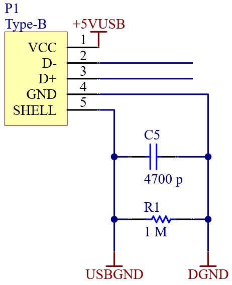
The shell of the USB Type-B connector is terminated to circuit ground using a 4700-pF capacitor in parallel with a 1-MΩ resistor.