Specifications
| Host Interface | USB 2.0 Type B FrontPanel Support |
| FPGA | XC6SLX45-2FGG XC6SLX150-2FGG |
| Memory | 16 MiByte DDR3, 16-bit wide data interface |
| NV Memory | 4 MiB System Flash (FPGA attached) |
| Oscillator | Programmable, 200 MHz max |
| FPGA I/O Voltage | See Powering the XEM6010 |
| MINIMUM | TYPICAL | MAXIMUM | UNITS | |
|---|---|---|---|---|
| DC Input | +4.5 | +5.0 | +5.5 | VDC |
| DC Input Ripple | – | – | 50 | mVp-p |
| Operating Temperature | 0 | – | +70 | ºC |
| Operating Temperature (Industrial Version) | -40 | – | +85 | ºC |
| Storage Temperature | -50 | 0 | +100 | ºC |
| Weight | 27 | grams | ||
| Oscillator Frequency | – | – | 200 | MHz |
| Oscillator Period Jitter | 400 | ps pk-pk |
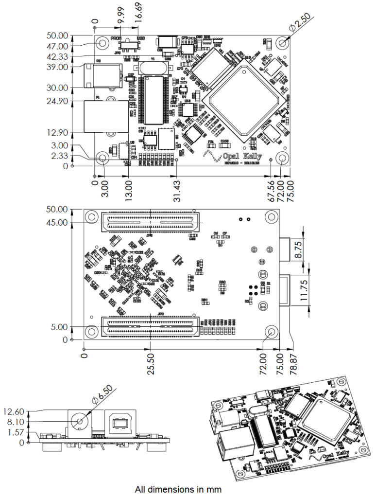
PCB Footprint
The PCB is 75mm x 50mm with four mounting holes (M2 metric screws) spaced as shown in the figures below. These mounting holes are electrically isolated from all signals on the XEM6010. The two connectors (USB and DC power) overhang the PCB by approximately 4mm in order to accommodate mounting within an enclosure.
The XEM6010 has two high-density 80-pin connectors on the bottom side which provide access to many FPGA pins, power, and JTAG.
BRK6110 Breakout Board
A simple breakout board (the BRK6110) is provided as an optional accessory to the XEM6010. This breakout board provides DC power and easy access to the high-density connectors on the XEM6010 by routing them to lower-density 2mm-spaced thru-holes. The breakout board also provides a convenient reference for building boards that will mate to the XEM6010.
Opal Kelly reserves the right to change the form-factor and possibly pinout of the BRK6110. Therefore, unlike the XEM6010, it is not intended or recommended for production integration.
Full schematics and Gerber artwork files for the BRK6110 are provided free of charge. If your application depends on the existing form-factor, you may reproduce this board from these documents.
A mechanical drawing of the BRK6110 is also shown at the end of this document.
Mechanical Drawing